
Choose the Right Wheels and Rollers for a Sliding or Swing Gate
Start with how the gate moves and where its weight is supported. Then match the hardware to the frame, track, mounting, clearance and documented load requirements.
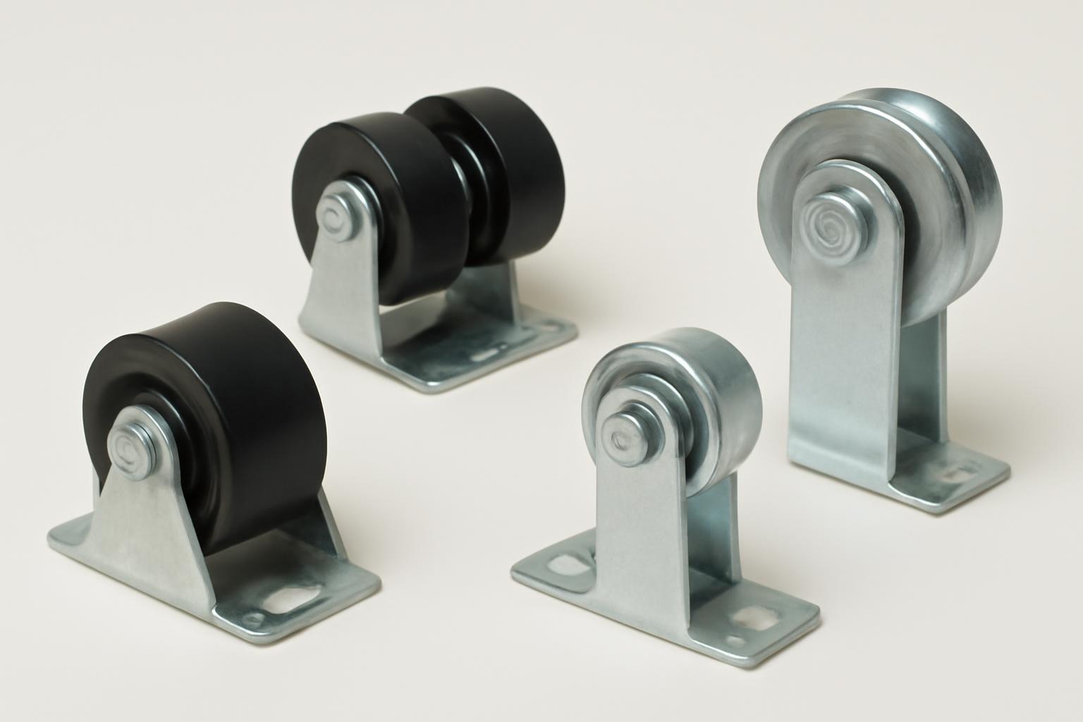
“Chain link gate rollers” is an umbrella term, not a single product. It may refer to cantilever rollers mounted on fixed posts, rear wheels that follow pipe tracks, a ground-contact wheel carrier, a V-groove wheel that runs on a dedicated rail, or a helper wheel attached to a hinged gate.
These parts are not interchangeable. Before comparing wheel diameter, material, or price, determine how the gate moves and where its weight is supported. Then match the hardware to the frame, posts, track, mounting method, travel surface, clearance, and documented load requirements.
For self-storage operators and property managers, that system-first approach is especially important because a dragging or binding access gate may have an alignment, track, frame, surface, or support problem rather than a defective wheel. This guide is a synthesis of supplier catalogs and installation instructions, not product testing or a substitute for the specifications of the actual gate, hardware, and operator.
Identify Your Gate System Before Shopping
Start with this decision tree:
-
Does the gate rotate on hinges? - Yes: It is a swing or drive gate. If its leading edge drags, you may need a helper or swivel wheel. - No: Continue.
-
Does the gate move sideways? - Yes: It is a sliding gate. Continue. - No: Stop and identify the gate before buying hardware.
-
Does a wheel near the front roll directly on the driveway or another travel surface? - Yes: It is probably a ground-rolling system using rear track wheels and a forward wheel carrier. - No: Continue.
-
Is the gate held between rollers attached to fixed posts and suspended above the travel surface? - Yes: It is probably a cantilever gate. - No: Look for a V-shaped rail, angle track, or another dedicated track system.
Cantilever gate
A cantilever gate slides sideways while rollers on fixed support posts carry and guide its frame. In the four-roller arrangement described by America’s Fence Store, two lower rollers support the gate and two upper rollers capture and guide it. No front wheel follows the ground in that arrangement. America’s Fence Store explains the documented cantilever layout.
Not every cantilever gate uses identical rollers or geometry. Post spacing, counterbalance length, frame construction, roller quantity, and mounting height must match the specific design.
Ground-rolling gate
A ground-rolling chain-link gate uses a different support path. In the Chain Link Fittings kit instructions, two rear wheels ride on parallel upper and lower pipe tracks while a double-wheel carrier near the leading end of the bottom rail transfers part of the gate’s weight to the travel surface. The rolling-gate kit instructions show this wheel arrangement.
This system depends on track alignment and the condition of the ground-wheel path. It should not be confused with a cantilever gate simply because both move parallel to a fence.
Track-based gate
Some catalogs place V-groove wheels, track rollers, carriage plates, and related hardware in the same category as conventional rolling-gate parts.
A pipe track roller must likewise match the track profile and dimensions. “Sliding gate wheel” does not provide enough information to establish suitability.
Swing-gate helper wheel
A helper wheel supports the moving end of a hinged swing or drive gate that would otherwise drag. Depending on the design, it may swivel as the gate changes direction or remain in a fixed orientation.
A documented retail example uses a solid-rubber swivel wheel for a 1-3/8-inch chain-link drive-gate frame, but the supplied listing does not publish a load capacity. It demonstrates a frame-fit specification, not proof that the wheel can support every gate made from that tube size. See the Everbilt swing-gate wheel listing.
It also is not an automatic repair for worn hinges, an unstable post, or a bent gate frame.
Quick identification checklist
Before searching by product name, record:
- Does the gate swing or slide?
- Does any wheel touch the ground?
- Are there upper and lower pipe tracks beside the fence?
- Are fixed rollers attached to support posts?
- Is there a V-shaped or angle track on the ground?
- Is the troublesome part at the front, rear, top, or bottom?
- Does the gate remain supported when the suspected wheel is unloaded?
- Is the existing item a complete assembly or only a wheel, bracket, guide, or cover?
What Each Roller, Wheel, Carrier, and Accessory Does
Gate-hardware categories often combine functional assemblies, individual replacement parts, and protective accessories. Identify the part’s role before comparing products.
| Part name | Gate system | Usual location | Role | Measurements to verify |
|---|---|---|---|---|
| Lower cantilever roller | Cantilever sliding gate | Fixed roller post, below gate frame | Carries the gate in a typical four-roller arrangement | Post shape and diameter, gate-rail shape and outside diameter, mounting clearance |
| Upper cantilever roller | Cantilever sliding gate | Fixed roller post, above gate frame | Captures and guides the gate while retaining clearance | Post and rail dimensions, mounting height, specified guide clearance |
| Rear track wheel | Ground-rolling sliding gate | Rear vertical gate member, near top or bottom | Travels on an upper or lower pipe track | Frame size, track diameter, wheel profile, guide position |
| Pipe track roller | Ground-rolling or track-based gate | Rear of gate or another system-specific track point | Rolls on compatible round track | Track outside diameter, groove, axle, bracket geometry |
| Double-wheel carrier | Ground-rolling sliding gate | Near front of bottom gate rail | Supports the leading portion of the gate on the ground | Frame size, carrier width, wheel diameter, axle, mounting method |
| Single-wheel carrier | Ground-supported gate | Bottom gate rail | Provides ground support through one wheel | Published rating, frame fit, wheel size, bracket width |
| Replacement wheel | Varies | Inside an existing carrier or bracket | Replaces only the rolling element | Diameter, width, hub bore, axle diameter, tread profile |
| Guide assembly | Rolling or track-based gate | Near a track or gate frame | Controls lateral position or helps retain the gate | Track profile, capture clearance, bracket pattern |
| Carriage plate | Track-based sliding gate | System-specific mounting point | Connects wheels or rollers to the gate structure | Bolt pattern, plate dimensions, axle spacing |
| V-groove wheel | Dedicated ground-track system | Bottom of sliding gate | Runs on matching V-track | Groove profile, track angle, wheel diameter, axle and mount |
| Helper or swivel wheel | Swing gate | Near the leading edge | Supports a hinged gate through its sweep | Frame diameter, mount position, caster geometry, surface clearance |
| Roller cover | Cantilever gate | Around a roller area | Shields part of the roller and reduces direct access | Roller size, upper or lower position, mounting compatibility |
| Track bracket | Ground-rolling gate | Fence or support posts | Holds and aligns track | Post diameter, track diameter, offset, clamp size |
| Gate stop or snow guard | Sliding gate | End of travel or near roller area | Limits movement or addresses a specific interference point | Gate path, stopping position, hardware compatibility |
| Latch | Any gate | Leading edge and latch post | Secures the closed gate | Gate-to-post gap, mounting bands, frame and post dimensions |
Cantilever supports and guides
In the documented four-roller arrangement, the lower rollers are the primary supports. The upper rollers capture and guide the upper frame while retaining enough clearance to prevent continuous pressure and binding.
Four loose rollers do not necessarily make a complete cantilever system. Mounting chassis, U-bolts, covers, stops, posts, and the gate’s counterbalance frame may be separate.
Rear wheels and forward carriers
On the documented ground-rolling arrangement, rear track wheels attach near the top and bottom of the gate’s rear vertical support. They travel along parallel tracks beside the fence. A double-wheel carrier mounts near the leading end of the bottom rail and rolls on the driveway or other prepared surface.
A carrier may be sold as:
- A complete bracket, axle, and wheel assembly
- A bracket without wheels
- A replacement carrier frame
- One replacement wheel
- A paired-wheel assembly
- A pneumatic- or solid-wheel configuration
Read the included-parts list rather than relying on the product image.
Helper wheels and accessories
Retailers list swing-gate helper wheels in swivel and non-swivel forms, but a product’s frame fit does not establish its load capacity or suitability for the ground conditions.
Accessories address different functions:
- Brackets support tracks or assemblies.
- Covers shield roller areas.
- Stops define the end of travel.
- Snow guards address particular interference points.
- Lower guides help retain rolling gates on their tracks.
- Latches secure gates when closed.
A catalog may place all of these beside chain link gate rollers. A cover, stop, bracket, loose wheel, or latch is not necessarily a functioning roller assembly.
Measure for Compatibility: Frame, Post, Track, and Mounting
Wheel diameter is only one measurement.
Take measurements at the gate and photograph the existing hardware from the front, rear, and side.
Printable measurement worksheet
- Gate movement
- [ ] Swing
- [ ] Cantilever slide
- [ ] Ground-rolling slide
- [ ] V-track or another track-based slide
-
[ ] Uncertain
-
Gate frame
- Shape: ____
- Measured outside diameter or width: ____
- Tubing specification, if marked: ____
-
Condition near mounting point: ____
-
Roller or support posts
- Round or square: ____
- Measured outside diameter or width: ____
- Distance between support posts: ____
-
Condition and alignment: ____
-
Track
- Type or profile: ____
- Measured outside diameter or width: ____
- Upper-to-lower track spacing: ____
- Bracket spacing: ____
-
Seam condition: ____
-
Existing wheel or roller
- Outside diameter: ____
- Tread or roller width: ____
- Hub width: ____
- Axle or bore diameter: ____
- Groove profile: ____
-
Material, if known: ____
-
Bracket or carrier
- Overall width: ____
- Inside mounting width: ____
- Bolt or U-bolt spacing: ____
- Axle position: ____
- Offset from frame: ____
-
Existing mounting location: ____
-
Clearance
- Ground clearance: ____
- Clearance around upper guides: ____
- Clearance from fences, posts, walls, and operators: ____
-
Available travel behind the opening: ____
-
Documentation to obtain
- Maximum gate weight: ____
- Rated load per wheel, roller, or assembly: ____
- Required number of rollers: ____
- Included fasteners: ____
- Bearing type: ____
- Lubrication instructions: ____
- Replacement part number: ____
- Operator compatibility: ____
Round and square frames are not interchangeable
Catalogs list separate hardware for round and square framing. One rolling-gate category includes filters for 1-1/2-inch round, 1-1/2-inch square, 1-5/8-inch round, 2-inch round, and 2-inch square frames. The same category contains single- and double-wheel carriers, rear wheels, track rollers, and V-groove products, showing why frame size alone cannot identify the required component. Review the Hoover Fence rolling-gate categories and frame filters.
Other listings identify helper wheels for 1-3/8-inch swing-gate frames. Cantilever catalogs add multiple round-post sizes, a 4-inch square-post option, and gate-frame examples such as 1-5/8-inch round and 2-inch square.
Nominal pipe size versus actual outside diameter
Pipe and gate framing may be described by nominal size, actual outside diameter, or a catalog convention. Those descriptions can appear contradictory. For example, one cantilever listing pairs a nominal 2-1/2-inch frame description with a stated 2-3/8-inch outside diameter. The Chain Link Fittings catalog shows nominal and outside-diameter examples.
Do not convert or guess from memory. Record the measured outside diameter and compare it with the exact manufacturer diagram, compatibility table, or written specification. If a listing gives only a nominal size, ask the seller or manufacturer to confirm the accepted outside-diameter range.
Track and bracket measurements
Documented rolling-gate brackets are offered for 1-5/8-inch track pipe or rail and for several post diameters. That does not make every bracket for that track size interchangeable. Offset, U-bolt size, sleeve arrangement, post fit, finish, and track orientation may differ.
Pre-order rules
Before ordering, obtain written confirmation of:
- The rated load for the individual part and complete arrangement
- Maximum permitted gate weight
- Required wheel or roller quantity
- Approved frame and post dimensions
- Axle diameter and bearing type
- Whether bearings are sealed or serviceable
- Lubrication requirements
- Included U-bolts, brackets, axles, nuts, and fasteners
- Approved track profile and dimensions
- Compatibility with the existing gate operator
- Replacement wheel and bearing part numbers
Retail category pages generally do not provide all of this engineering information. If the seller cannot document load capacity or fit, do not treat a matching product title as proof of suitability.
Never infer cross-brand compatibility merely because two listings use the same nominal tube dimension.
Steel, Nylon, Polymer, and Rubber Options
Material descriptions may refer to different portions of an assembly. A “steel roller assembly” can have a steel chassis and a nylon roller. A wheel carrier may use a galvanized bracket with rubber wheels. Confirm the materials used for the rolling surface, hub, bearing, axle, bracket, and supporting structure.
Retail catalogs document several broad categories:
- Steel and nylon track wheels
- Aluminum, polymer, and steel category filters
- Nylon or polymer cantilever rollers
- Steel cantilever chassis or assemblies
- Hard-rubber carrier wheels
- Pneumatic-rubber carrier wheels
- Solid-rubber swing-gate wheels
The JakeSales catalog, for example, places steel and nylon track wheels, hard-rubber and pneumatic carriers, helper wheels, and cantilever rollers in one broad gate-parts category. See the documented gate-wheel and roller categories.
Steel and nylon cantilever rollers
One specialist installation guide describes certain steel cantilever rollers as having grease fittings and certain nylon rollers as using sealed bearings. That distinction applies only to the product families described in that guide; it is not a universal rule for all steel and nylon rollers. Hoover Fence’s cantilever guide provides the product-specific bearing descriptions.
For any material, ask:
- Is the rolling surface compatible with the track or ground?
- What bearing design is used?
- Is lubrication required, allowed, or prohibited?
- What corrosion protection is applied to the chassis, axle, and fasteners?
- Can the wheel or bearing be replaced separately?
- Is the material approved for the expected temperature and weather exposure?
- If the wheel is pneumatic, how is pressure checked and maintained?
- Does the published rating apply to one wheel, one carrier, or the complete system?
Galvanized hardware may help limit corrosion, but it still requires inspection.
The available evidence does not establish a dependable ranking of steel, nylon, polymer, solid rubber, hard rubber, or pneumatic rubber for lifespan, noise, rolling resistance, weather performance, corrosion resistance, or maximum load. Those comparisons require specifications or testing for the exact products and operating conditions.
Treat words such as “heavy-duty,” “professional-grade,” “smooth,” “durable,” and “maintenance-free” as marketing unless they are supported by useful load, cycle, bearing, environmental, and maintenance data. Documented capacity and exact fit matter more than adjectives in a listing title.
Complete Kits, Assemblies, and Replacement Parts
Classify the product before comparing prices.
1. Complete system or hardware kit
A kit groups several components for a defined gate arrangement. One documented rolling-gate kit includes six universal track brackets, two 1-5/8-inch rear-wheel brackets, two pipe track rollers, one 6-inch double-wheel carrier with two wheels, and one rolo latch. The supplier’s kit instructions identify those contents.
Even a “hardware kit” may exclude the gate frame, track pipe, support posts, concrete, excavation, specialized fasteners, tools, surface preparation, labor, and operator components. Compare the packing list with the installation drawing and the site conditions.
2. Functional assembly
A functional assembly is a working unit such as:
- A cantilever roller with mounting chassis
- A rear track wheel with bracket
- A double-wheel carrier with axle and wheels
- A guide assembly
- A carriage plate with installed rollers
An assembly may still exclude U-bolts, frame clamps, post brackets, or replacement fasteners. Verify the packing list rather than assuming the mounting hardware is included.
3. Replacement component
Replacement components include:
- Loose wheels
- Bearings
- Axles
- Rear-wheel brackets
- Carrier frames
- Individual track rollers
- U-bolts and mounting hardware
Before replacing only a wheel, inspect the axle, bearings, carrier, brackets, fasteners, track, and gate frame.
As a conservative purchasing principle, consider replacing the complete assembly when:
- The carrier is bent
- The axle or bearing specification is unknown
- Mounting components are damaged
- The bracket no longer clamps securely
- Structural hardware has substantial corrosion or distortion
- Replacement-wheel compatibility cannot be verified
That is an inspection principle, not a universal manufacturer requirement. A loose replacement wheel is more reasonable when the manufacturer identifies it as compatible and the existing axle, bearing arrangement, carrier, brackets, frame, and track remain serviceable.
4. Optional or protective accessory
Accessories include:
- Upper or lower roller covers
- Gate stops
- Snow guards
- Wall-mounted track brackets
- Chain-link-mounted track brackets
- Lower lift-off guides
- Latches
These products solve different problems and should not be assumed to come with a wheel or carrier.
Price is only a screening tool
The undated catalog evidence supplied for this guide illustrates the spread between accessories and complete assemblies: one cantilever category displayed a stop bracket at $22.58 and a large roller assembly at $236.41. Those figures are historical catalog observations, not current quotes or evidence of delivered value. The cited cantilever catalog contains the underlying product examples.
Displayed price does not establish delivered or installed cost. Configuration choices, freight, taxes, availability, posts, track, concrete, equipment, labor, operator integration, and site correction may be separate.
Installation Fundamentals for Cantilever and Ground-Rolling Gates
Cantilever and ground-rolling systems use different support paths. Do not combine their roller locations or transfer dimensions from one arrangement to the other.
The following steps summarize documented vendor arrangements. They are not universal engineering instructions. Use the drawings and specifications for the actual gate and hardware.
Cantilever installation path
For the cited four-roller arrangement:
- Mount one lower support roller on each roller post.
- Place straight tubing or rail across the lower rollers.
- Put a level on that tubing.
- Adjust the second roller until it aligns with the first.
- Tighten the mounting hardware.
- Support and raise the gate onto the lower rollers.
- Install the two upper rollers to capture and guide the upper frame.
- Retain the clearance required by the actual hardware.
Published retailer guides differ slightly on upper-guide clearance. One gives approximately 1/2 inch, while another specifies 1/4 to 1/2 inch. Those are source-specific dimensions, not universal settings. Hoover Fence’s installation guide documents the latter range and leveling method.
The gate should be centered and balanced on the lower rollers before the upper guidance is finalized. Upper rollers should control the frame without being tightened so firmly that they create constant friction.
Keep roller areas clear of grade, snow, ice, and frozen ground, while preserving the mounting height and capture geometry required by the manufacturer.
Ground-rolling installation path
In the documented rolling-gate arrangement:
- Install and support parallel upper and lower tracks.
- Keep their spacing consistent throughout the gate’s travel.
- Join track sections tightly so wheels do not catch at raised or loose seams.
- Mount the rear track wheels on the outside face of the rear vertical support, near its top and bottom.
- Mount the double-wheel carrier as far forward as practical on the bottom horizontal member.
- Place both rear wheels on their respective tracks.
- Adjust the lower guides to retain the track without creating binding.
- Test the complete travel before final tightening.
Some double-wheel carriers include an axle trim bolt for correcting the gate’s direction during test travel. Use that feature only when the specific carrier provides it, and make small adjustments while retesting.
One manufacturer guide specifies support posts on 8-foot centers, track brackets approximately 1 foot from the top and bottom, and particular minimum post dimensions. Those figures apply to the described kit rather than every rolling gate. The XCEL rolling-gate guide documents its system-specific placement.
Commissioning checklist
Before regular use:
- Move the gate through its complete opening and closing travel.
- Watch every wheel, roller, guide, seam, and bracket.
- Listen and feel for recurring catches or rough rotation.
- Check whether the gate drifts when released.
- Confirm upper-guide and lift-off-guide clearance.
- Verify that carrier wheels remain on the intended path.
- Check that tracks remain parallel and securely supported.
- Tighten loose nuts, bolts, U-bolts, brackets, and axle hardware.
- Confirm that stops prevent excessive travel.
- Verify that the latch engages without pulling the gate out of alignment.
- Recheck alignment after several complete cycles.
Troubleshoot Dragging, Binding, Sagging, and Uneven Travel
Do not begin by ordering a new wheel. Use a controlled diagnostic sequence:
- Secure the gate against unexpected rolling, swinging, or falling.
- Clean debris from the track and travel surface.
- Inspect the frame and posts for bending, cracking, displacement, or corrosion.
- Check mounting hardware and fasteners.
- Examine wheels, rollers, axles, and bearings.
- Check track alignment, spacing, support, and seams.
- Verify guide and capture clearance.
- Move the gate slowly through its complete travel and record where the problem begins.
A swing gate drags
Check:
- Whether the gate has sagged out of square
- Hinge wear or looseness
- Hinge-post movement
- Helper-wheel mounting position
- Compatibility with the gate-frame diameter
- Changes in ground height through the swing arc
- Cracks, ruts, and surface transitions
- Whether a swivel wheel turns freely
A helper wheel can provide ground support, but it cannot restore a bent frame, failing hinge, or moving hinge post.
A rolling gate catches
Inspect:
- Loose or raised track seams
- Tracks that are no longer parallel
- Changing spacing between upper and lower tracks
- Loose track brackets
- Dirt, stones, ice, or vegetation
- Chipped, flattened, cracked, or deformed wheels
- Bent wheel brackets
- Guides tightened enough to create friction
Correct track support and alignment before using a carrier adjustment to compensate for poor travel.
The gate can be lifted off its track
Inspect the lower guides and the entire capture arrangement. The guides should resist easy lift-off without pressing so firmly that the wheels bind during normal travel.
Tightening every guide is not necessarily the answer. Excessive capture pressure may replace derailment risk with continuous drag.
A rolling gate veers
Check whether the tracks are straight, parallel, consistently spaced, and securely supported. Inspect the carrier mounting and verify that both ground wheels rotate correctly.
If the installed carrier has an axle trim bolt, follow its adjustment procedure only after checking the track, frame, wheel condition, and mounting hardware.
A cantilever gate binds
Verify that the two lower support rollers are level with each other and aligned with the gate’s path. Inspect the upper guidance for excessive pressure or inadequate clearance. Depending on the documented hardware arrangement, an interfering upper roller may need to be raised while the required capture clearance is retained.
Also inspect roller-post movement, loose U-bolts, frame deformation, obstructions, and changes in grade around the rollers.
The gate sags or balances poorly
Inspect the:
- Gate frame and bracing
- Support, roller, and latch posts
- Lower cantilever roller positions
- Forward wheel carrier
- Rear-wheel brackets
- Hinges on a swing gate
- U-bolts, clamps, axles, and frame connections
Wheel replacement is not a structural repair.
Observable replacement indicators include:
- Visibly damaged tread
- A cracked or deformed wheel
- Seized or rough rotation
- A bent carrier
- A loose or damaged axle
- A cracked or distorted bracket
- Recurrent derailment after alignment and capture checks
No universal replacement interval or service-life estimate is supported by the available evidence. Inspect actual condition and follow the maintenance instructions for the exact product.
Travel Surface, Weather, Safety, and Professional Review
Ground-contact wheels need a continuous, serviceable path. Inspect the entire route, including the area occupied when the gate is fully open.
Look for:
- Concrete-to-asphalt transitions
- Broken pavement and raised joints
- Ruts or depressions
- Gravel migration
- Drainage channels
- Debris and vegetation
- Changes in grade
- Water that freezes in the wheel path
- Snowbanks or plowed material
- Insufficient clearance at the open position
The available evidence does not support recommending a particular tread for concrete, asphalt, gravel, or uneven ground. Ask the manufacturer to confirm surface suitability and load capacity for the exact wheel.
Slope and weather
Slope is both a performance and safety concern. A heavy sliding gate can move unintentionally downhill if it is not adequately controlled. A ground-rolling gate still needs a stable wheel path and a complete system designed for the site conditions.
Snow, ice, frozen ground, and water-collecting depressions can obstruct travel or affect alignment. Cantilever guidance recommends keeping rollers above grade so accumulated snow or frozen ground does not surround them. The same guidance warns that heavy gates can be awkward to handle, that rollers create pinch points, and that excessive slope can create dangerous downhill movement. America’s Fence Store addresses these installation hazards.
Handling and pinch points
Support the gate before loosening rollers, hinges, carriers, brackets, or other load-bearing hardware. Use enough people or suitable lifting equipment to prevent uncontrolled movement, and do not work beneath or beside an unsecured gate.
Posts, footings, and automated gates
Before digging for posts or footings, arrange for underground utilities to be located. Check applicable permits, property setbacks, frost conditions, and local construction requirements. Footing dimensions depend on the location, soil, frost depth, gate design, and governing rules.
Automated gates require additional review. Consult the exact operator manual and qualified gate guidance before changing rollers, alignment, resistance, stops, or travel. One retailer guide references UL 325 in its powered-gate discussion, but that reference does not establish that any gate, roller, operator, or installation discussed here complies with that standard.
Seek manufacturer or qualified professional review when:
- The gate’s weight or the hardware load rating is unknown
- The gate is automated
- Posts, hinges, brackets, or frames are damaged
- The opening is unusually large
- The site has a significant slope
- Track supports or footings require reconstruction
- The gate cannot be safely supported during the work
- Replacement compatibility cannot be documented
Frequently Asked Questions
How many rollers does a chain-link sliding gate need?
It depends on the system and the manufacturer’s design.
The documented cantilever arrangement uses two lower support rollers and two upper guide rollers. A documented ground-rolling arrangement uses two rear track wheels and a forward double-wheel carrier. These are examples, not universal counts. The manufacturer rolling-gate guide shows its specified wheel arrangement.
Other track systems, gate sizes, frame designs, and engineered assemblies may require different hardware. Follow the gate or hardware manufacturer’s drawing.
Can I add a wheel to a chain-link swing gate that drags?
Possibly. Helper wheels are sold in swivel and non-swivel forms for swing and drive gates. The wheel must match the frame shape and diameter, mounting arrangement, required clearance, travel surface, and documented load.
First inspect the hinges, posts, frame, sag, and complete ground sweep. A helper wheel may support the leading edge, but it should not conceal structural damage or unstable hinges.
Are nylon chain link gate rollers better than steel rollers?
Not universally. Product-specific guidance describes some steel rollers with grease fittings and some nylon rollers with sealed bearings, but that distinction does not apply to every product. “Steel” or “nylon” may also describe only one part of an assembly.
The available evidence does not establish which material has the longest life, lowest noise, least rolling resistance, best weather performance, or highest capacity. Compare documented load rating, bearing design, lubrication requirements, corrosion protection, replaceability, exact fit, and environmental suitability.
Why does my rolling gate keep binding or moving off course?
Possible causes include:
- Tracks that are not parallel
- Inconsistent track spacing
- Loose brackets or track seams
- Debris, ice, or damaged pavement
- Damaged wheels or bearings
- Bent carriers
- Guides tightened enough to create drag
- An incorrectly aligned forward carrier
- Loose frame or axle hardware
Clean and inspect the system before adjusting it. Correct track alignment, track support, and guide clearance first. If the specific carrier includes an axle trim bolt, use it only for final travel-direction adjustment after the rest of the system has been checked.
Does a rolling-gate hardware kit include everything needed for installation?
Not necessarily. A documented kit includes track brackets, rear-wheel hardware, pipe track rollers, a double-wheel carrier, and a latch, but that does not mean every kit contains the same parts.
Track pipe, posts, the gate frame, concrete, excavation, tools, surface work, operator components, and some mounting hardware may be separate. Compare the packing list with the installation drawing and site requirements before ordering.
The safest purchasing sequence is straightforward: identify how the gate is supported, classify the required part, record every relevant frame, post, track, wheel, bracket, and clearance measurement, and diagnose alignment or site problems before replacing hardware. Then obtain the manufacturer’s exact specifications for load, bearings, fasteners, quantity, and compatibility. Fit and documented capacity matter more than “heavy-duty” labels, while heavy, sloped, damaged, or automated gates warrant qualified review.