
How to Plan a Rolling Gate That Fits, Tracks, and Latches Properly
For manual, ground-supported gates, reliable operation needs adequate runback and a firm wheel path. Tracks, pipe, overlap and latch alignment also matter.
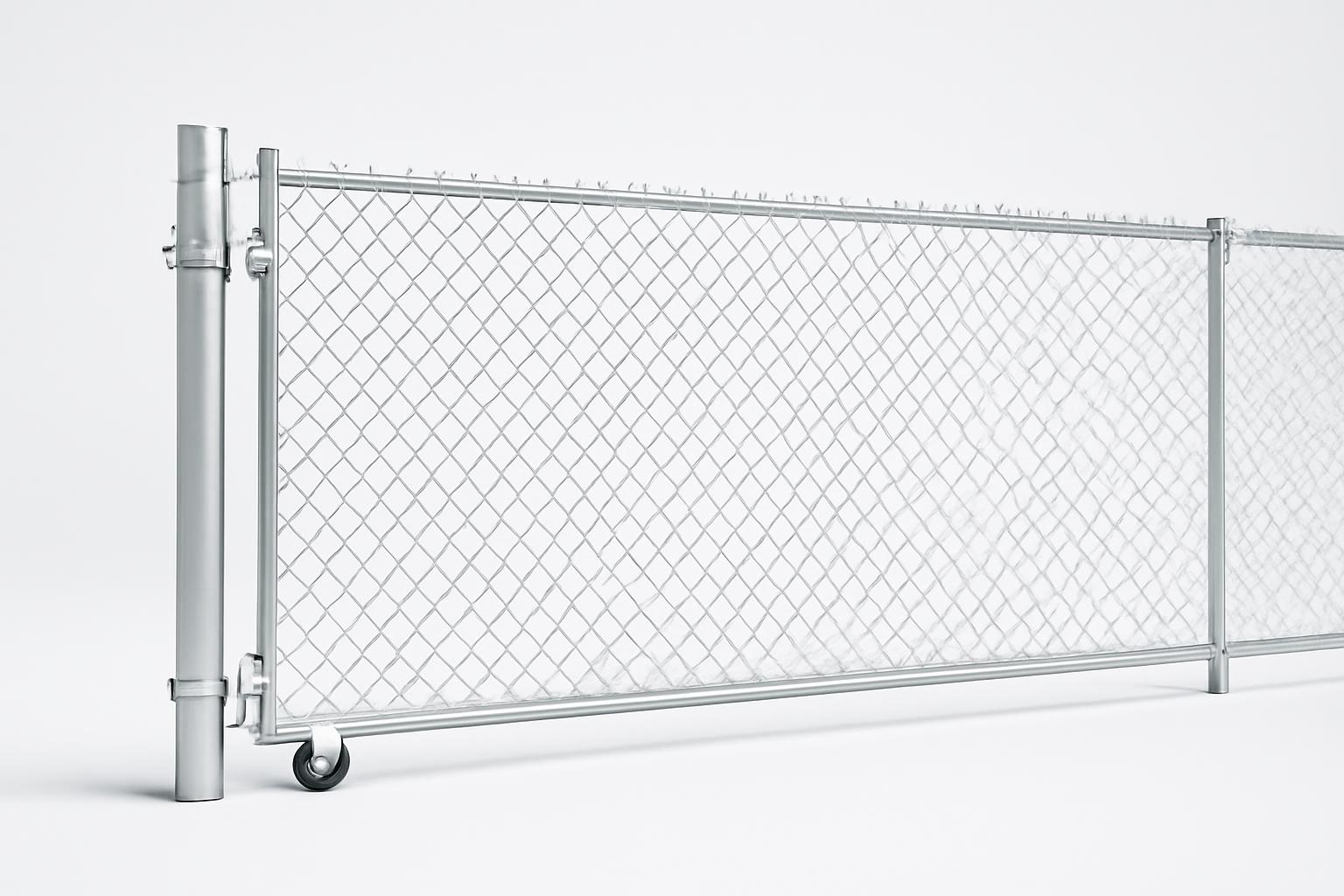
A chain link fence rolling gate opens parallel to the fence rather than sweeping across a driveway or yard.
Reliable operation depends on much more than attaching wheels to a chain-link panel. The site needs adequate runback, a firm wheel path, aligned tracks, compatible pipe and hardware, sufficient panel overlap, and a latch that remains aligned throughout the gate’s travel.
This guide covers purchasing, sizing, and installation planning for a manual, ground-supported rolling gate. It does not provide footing design, structural calculations, powered-gate safety design, or a universal installation procedure. Follow the exact manufacturer’s documentation and refer site-specific questions to a qualified gate installer, permitting authority, or engineer.
What a chain-link rolling gate is—and what it is not
The design covered here retracts along the adjoining fence line. Two rollers near the rear of the panel typically travel on upper and lower horizontal pipe tracks. A double-wheel carrier beneath the front supports the latch side and runs on the driveway or another prepared surface.
The following plan views are conceptual and not to scale:
CLOSED POSITION — PLAN VIEW

                    REQUIRED RUNBACK / STORAGE AREA
     <-------------------------------------------------------->

 Fence line and tracks
 =============================================================

 [rear rollers] [------ FINISHED GATE PANEL ------] | LATCH |
                  \_____ CLEAR OPENING _________/     POST

                                          ◎
                                 Front wheel carrier

 -------------------------------------------------------------
                       Firm wheel path

 Gate opens toward the runback  ←
FULLY OPEN POSITION — PLAN VIEW

                    REQUIRED RUNBACK / STORAGE AREA
     <-------------------------------------------------------->

 Fence line and tracks
 =============================================================

 [rear rollers] [------ FINISHED GATE PANEL ------] ◎

                                      |<-- CLEAR OPENING -->|
                                      |                     |
                                      |                 LATCH
                                      |                  POST

 -------------------------------------------------------------
                       Firm wheel path
The coordinated parts are:
- Clear opening: the usable width between gate posts when the gate is fully open.
- Latch post: the post that receives the front gate frame when the gate closes.
- Gate panel: the framed chain-link leaf, normally longer than the clear opening.
- Front carrier: the ground-running wheel assembly supporting the latch side.
- Rear rollers: assemblies that support and retain the back of the gate.
- Upper and lower tracks: horizontal pipes mounted beside the fence.
- Support posts: posts carrying the track brackets and tracks.
- Wheel path: the surface beneath the front carrier.
- Runback: the fence-line area occupied by the fully opened panel.
- Overlap: the portion of the finished panel extending beyond the nominal opening to accommodate the operating hardware and closure.
A swing gate rotates on hinges and needs an unobstructed arc in front of or behind the opening. A rolling gate removes that arc, but it does not remove the need for space. The complete panel must still retract beside the opening.
A cantilever gate uses post-mounted rollers and a counterbalanced frame rather than a front wheel running on the ground. These support arrangements are structurally different, so their post layouts, hardware, operators, and installation instructions are not interchangeable. TYMETAL’s comparison illustrates the basic roller-versus-cantilever distinction, although its comparative performance statements are manufacturer marketing rather than universal findings.
Product listings sometimes use “rolling,” “sliding,” “cantilever,” and “track gate” loosely. Before comparing prices or hardware, identify exactly how the proposed gate is supported.
Decide whether the site is suitable before choosing a gate
The front carrier makes the ground part of the operating system.
Site-readiness checklist
Inspect the complete routes traveled by the panel, front carrier, and rear rollers:
- Runback: Is there enough uninterrupted fence line to store the complete panel?
- Wheel-path firmness: Will the carrier run on concrete, sound asphalt, or another stable surface?
- Surface smoothness: Are there potholes, raised joints, roots, broken pavement, or abrupt seams?
- Longitudinal grade: Will the gate tend to roll downhill or become difficult to move uphill?
- Cross-grade: Does the surface slope sideways across the carrier’s route?
- Drainage: Does water collect or carry sediment over the wheel path?
- Snow and ice: Will accumulation regularly obstruct the carrier or tracks?
- Mud and gravel: Can loose material collect beneath or ahead of the wheels?
- Debris: Are leaves, stones, trash, or stored materials likely to enter the route?
- Pavement condition: Is asphalt already soft, cracked, or rutted?
- Fence-line obstructions: Do buildings, meters, downspouts, vegetation, bollards, or parked vehicles intrude into the runback?
- Animal containment: Is the expected opening beneath the frame acceptable?
Retailer guidance generally favors a smooth, firm wheel route such as concrete or asphalt. Hoover Fence also warns that snow and debris can obstruct the carrier and that wheels on heavy gates can rut asphalt. Its overview reports an under-gate clearance of approximately 3–6 inches, but actual clearance depends on the carrier, frame, grade, and adjustment. See Hoover Fence’s ground-path and clearance discussion.
That gap is particularly important where the fence is expected to contain pets or other animals. Chain-link fabric extending to the bottom rail does not eliminate the clearance created by an under-gate carrier.
What about a sloped driveway?
The available evidence does not establish a universal maximum slope or cross-grade. Some sellers describe rolling gates as suitable for sloped openings, while installation guidance emphasizes a smooth or level travel surface. Treat “works on slopes” as a product claim, not a design rule.
Record wheel-path elevations at the closed position, midpoint, and fully open position. Ask the selected supplier or installer to assess the measured grade and surface. Do not rely on a general product-category description.
When to compare a cantilever gate
A cantilever system deserves evaluation when:
- the site cannot provide a stable wheel path;
- snow, ice, mud, gravel, or debris will repeatedly obstruct a carrier;
- the driveway has difficult changes in grade;
- pavement rutting is a concern;
- the panel must remain clear of the ground; or
- future automation is an important objective.
A cantilever gate requires a counterbalanced frame and a different support-post arrangement. Its structural and runback requirements must be evaluated independently rather than borrowed from a ground-supported design.
Go/no-go decision
-
Is there enough uninterrupted runback for the complete panel and hardware? - No: Stop and compare a swing, double-swing, cantilever, or site-specific alternative. - Yes: Continue.
-
Can the front carrier travel on a firm, smooth, drainable route? - No: Improve the surface, obtain design-specific advice, or compare a cantilever system. - Yes: Continue.
-
Are grade, drainage, snow, debris, pavement, and containment concerns manageable? - Uncertain: Send photographs and elevation measurements to the supplier or installer. - Yes: Proceed to detailed measurement.
Measure the opening, runback, height, and wheel path
Measure before choosing a panel and again before authorizing fabrication. Do not substitute the stated width of an old gate, driveway, or fence bay for the actual opening between posts.
Measure inside to inside between the gate posts at both the top and bottom, keeping the tape on a level plane instead of following sloping ground. America’s Fence Store requests accuracy within plus or minus 1/8 inch and a separate inside-to-inside measurement between the adjoining support posts. That accuracy is a supplier-specific ordering target, not a universal construction tolerance. Its guide also says the inside spacing between supporting line posts should not exceed 8 feet for the described arrangement. Review the supplier’s measurement method and system-specific spacing.
Measurement worksheet
| Field | Site measurement or answer |
|---|---|
| Clear opening, measured level at top | |
| Clear opening, measured level at bottom | |
| Desired finished gate height | |
| Existing fence height | |
| Available runback length | |
| Distance between track-support posts | |
| Wheel-path elevation at closed position | |
| Wheel-path elevation at midpoint | |
| Wheel-path elevation at fully open position | |
| Cross-grade or side-to-side change | |
| Surface changes, joints, or obstructions | |
| Latch-post outside diameter | |
| Gate-frame outside diameter | |
| Track-post outside diameter | |
| Proposed track-pipe outside diameter | |
| Track-pipe wall specification | |
| Estimated or documented gate weight | |
| Required bottom clearance | |
| Pet or animal-containment concern | |
| Drainage, snow, mud, or debris notes |
Opening width is not finished panel length
The finished panel must extend beyond the clear opening. That additional length accommodates the rear hardware and allows the front frame to close into the latch.
One America’s Fence Store product is fabricated one foot longer than its ordered opening, but the same listing identifies the purchase as the gate alone and excludes hardware and posts. That extension is a product-specific example, not a universal overlap rule. See the documented panel extension and exclusions.
Obtain these three dimensions in writing:
- ordered clear opening;
- required overlap beyond the opening; and
- actual finished panel length.
Compare the finished length with the usable runback. Allow for rear hardware, stops, brackets, and clearance from adjacent structures.
Height requires more than the fence height
The carrier determines where the bottom horizontal frame sits above the wheel path. A panel ordered solely by fence height may therefore finish too high, too low, or at the wrong elevation for the tracks and latch.
Confirm:
- finished frame height;
- carrier model, wheel size, and mounting position;
- expected ground clearance;
- upper and lower track elevations;
- latch engagement height; and
- any approved top extension.
Post spacing is also system-specific. One installation manual calls for track posts on 8-foot centers, while another supplier limits the inside spacing of supporting line posts to 8 feet for its described arrangement. Neither figure should be applied to a different system without confirmation.
Final pre-order verification
Send the selected supplier or installer:
- top and bottom opening measurements;
- usable runback;
- desired height and bottom clearance;
- post locations and outside diameters;
- gate-frame and proposed track-pipe dimensions;
- wheel-path material and elevation changes;
- photographs of the opening and runback;
- documented or estimated gate weight;
- finish and chain-link infill specifications;
- intended latch; and
- any future automation objective.
Request written confirmation of the finished panel dimensions, overlap, carrier selection, track specification, post requirements, gate-weight limit, and complete hardware list.
Build the complete parts list and verify compatibility
A functioning rolling gate is a coordinated system. A complete project may require:
- fabricated gate panel or frame;
- chain-link fabric;
- tension bars, bands, ties, and other fabric hardware;
- front double-wheel carrier;
- two rear track rollers or wheel assemblies;
- upper and lower track pipe;
- track brackets;
- track-support posts;
- latch post;
- latch;
- brace bands, end bands, U-bolts, and mounting hardware;
- stops, retainers, or safety brackets where specified;
- nuts, bolts, and fasteners;
- concrete; and
- wheel-path or pavement work.
The front carrier supports the latch side and establishes ground clearance. The rear rollers support and retain the back of the panel on the tracks. Brackets transfer track loads to the posts.
A documented kit example
A JakeSales kit listing identifies a 6-inch double-wheel carrier, two rear rollers, six track brackets, one rolo latch, and associated mounting hardware. The same listing says that the two brace bands required to attach the latch are not included. Track pipe, posts, and the panel are also outside the stated kit contents. Review the kit contents, dimensions, and exclusions.
A product photograph or the phrase “complete kit” is not a packing list. Verify every component by model and quantity.
Compatibility table
Complete this table from the documentation for the exact products being purchased:
| Component | Required gate-frame OD | Track-pipe OD and wall | Required post OD | Wheel size | Mounting hardware | Rated gate weight |
|---|---|---|---|---|---|---|
| Front carrier | N/A | N/A | ||||
| Upper rear roller | N/A | |||||
| Lower rear roller | N/A | |||||
| Track brackets | N/A | N/A | ||||
| Latch | N/A | N/A | N/A | |||
| Rear-wheel bracket | N/A | |||||
| Stop or safety bracket | N/A | |||||
| Upper track | N/A | N/A | ||||
| Lower track | N/A | N/A |
A 1-5/8-inch track-pipe dimension appears in several systems, while individual connections may be listed for 1-5/8-inch or 1-7/8-inch gate frames. The JakeSales listing also specifies outside-diameter measurements and warns through its component details that the latch, carrier, rollers, and brackets do not all share the same fit range. Matching one pipe number does not establish system compatibility.
Check every connection independently:
- carrier U-bolt to gate frame;
- rear bracket to the rear vertical frame;
- roller profile to track pipe;
- bracket sleeve to track pipe;
- bracket U-bolt to support post;
- latch body to gate frame;
- latch bands to latch post; and
- stops or retainers to their intended members.
Product titles can be broader than the detailed specifications. If a title suggests wide post compatibility but the latch details give a narrower range, treat the component-level requirements as controlling and resolve the conflict before ordering.
The available product pages do not provide independent load tables or prove cross-manufacturer compatibility. Obtain gate-weight limits, wheel capacity, bracket capacity, track specification, and frame limits from the selected system’s documentation.
Compare gate-only listings, hardware kits, and complete systems
Listings that look similar in search results can represent materially different purchases. Compare scope before comparing price.
Inclusions matrix
| Purchase category | Documented example | Likely or stated exclusions |
|---|---|---|
| Fabricated gate panel | A welded rolling-gate panel with chain-link infill | Hardware, posts, tracks, carrier, rear rollers, brackets, latch components, concrete, freight, and installation may be separate |
| Rolling-gate hardware kit | Carrier, rear rollers, track brackets, latch, and selected mounting hardware | Panel, fabric, track pipe, posts, concrete, and some latch bands |
| Complete DIY component system | Frame pieces, chain-link infill, posts, tracks, and hardware as listed by the seller | Concrete, site preparation, tools, labor, permits, and potentially freight |
| Engineer-sealed evaluation or plan | A permit-support document within a defined scope | The physical gate, hardware, installation, and design outside the document’s limits |
Exact retailer prices have been omitted because the supplied listings do not provide reliable observation dates and prices can change by size, finish, stock, and destination. The important comparison is scope: a panel, hardware kit, component package, and engineering document are not equivalent purchases.
A DIY package can be broader than a hardware kit. One listed self-assembly system says it includes frame pieces, chain-link infill, posts, tracks, and hardware, while concrete remains separate. See the stated DIY package scope.
An engineer-sealed evaluation is a document rather than a shipment of gate components. One documented generic evaluation applies to a stated 8-foot-high by 25-foot-wide configuration and requires site-specific engineering outside its scope. Review the engineering document’s stated scope.
Quote-comparison checklist
Require every quote to identify:
- clear opening and finished panel dimensions;
- finished panel length and overlap;
- frame outside diameter and wall specification;
- frame bracing or trussing, if applicable;
- fabric gauge, aperture, selvage, and finish;
- front-carrier model and wheel size;
- rear-roller models and quantities;
- track-pipe outside diameter, wall specification, and total length;
- track-bracket models and quantities;
- support-post and latch-post quantities, sizes, and finishes;
- latch model, mounting bands, and padlock provisions;
- stops, retainers, guards, or safety brackets;
- concrete and surface-work responsibility;
- freight, unloading, and damage-inspection terms;
- lead time and fabrication-approval process;
- installation and adjustment responsibility;
- permit and engineering responsibility; and
- warranty scope and exclusions.
Total-project cost worksheet
| Cost line | Budget |
|---|---|
| Fabricated panel or frame | |
| Chain-link fabric and attachment hardware | |
| Front carrier | |
| Rear rollers and brackets | |
| Track brackets | |
| Upper and lower track pipe | |
| Support posts and latch post | |
| Latch and mounting bands | |
| Stops, guards, or retainers | |
| Concrete | |
| Wheel-path or pavement work | |
| Finish or color surcharge | |
| Freight and unloading | |
| Tools or equipment rental | |
| Installation labor | |
| Permit fees | |
| Engineering or sealed plans | |
| Approved operator and controls, if applicable | |
| Contingency for field corrections | |
| Total planned project cost |
Compare complete delivered scope rather than headline price.
Installation sequence: from track posts to final latch adjustment
This section is an installation-planning overview, not a stand-alone installation manual. The sequence summarizes what a buyer should expect and verify. It does not establish footing dimensions, structural capacity, wind resistance, or suitability for a particular site.
1. Complete preliminary checks
Before digging or modifying the fence:
- confirm relevant property boundaries and setbacks;
- ask the local authority whether permits or approved plans are required;
- arrange utility locating before excavation;
- verify the opening and runback measurements;
- inspect delivered parts against the packing list;
- resolve damaged, missing, or incompatible components; and
- read the exact manufacturer’s instructions.
Hoover Fence’s cantilever-gate guide recommends checking permits, restrictions, property lines, and buried utilities before excavation. Those preliminary checks are broadly relevant, but its cantilever-specific post, footing, roller, and operator details must not be transferred to a ground-supported gate. See the preliminary site checks.
2. Establish the track-support posts
Set or verify the posts that will carry the upper and lower tracks. Their position affects track straightness, spacing, and the available runback.
One rolling-gate kit manual specifies support posts on 8-foot centers, at least 2-1/2-inch Schedule 40, with brackets approximately one foot above the fence bottom and one foot below the top. It also specifies 1-5/8-inch Schedule 40 track pipe. These dimensions apply to that supplier’s example and are not universal. Consult the system-specific installation manual.
Do not infer footing depth or diameter from the post specification.
3. Install the upper and lower brackets
Place the brackets at the elevations required by the selected system. Keep each row straight and maintain the specified separation between the upper and lower tracks.
Check spacing at every support post.
4. Cut and fit the track pipe
Fit sections as directed so a projecting seam cannot catch a roller.
Verify that:
- both tracks are straight;
- joints do not create shoulders or gaps;
- upper and lower tracks remain parallel;
- fasteners do not intrude into wheel travel; and
- the available track length supports the fully opened panel.
5. Mount the rear rollers
The cited kit manual places the rear rollers on the outside of the rear vertical frame member, approximately one foot from the top and bottom. That is a system-specific arrangement. Confirm the orientation, spacing, and attachment method for the actual panel and roller assemblies.
Install the rollers provisionally so final adjustment remains possible after the panel is placed on the tracks.
6. Attach the front carrier
The same example manual initially places the double-wheel carrier as far forward as practical on the lower horizontal frame member. Confirm the correct orientation and clamping arrangement for the selected carrier.
If the carrier includes an axle trim bolt or another tracking adjustment, identify its neutral position and adjustment procedure before placing the gate.
7. Place and retain the gate
A large panel can fall or move unexpectedly during lifting and adjustment. Support it with suitable equipment, keep bystanders clear, and do not rely on partially tightened wheel hardware to hold it.
Seat the rear rollers on their tracks and place the front carrier on the intended wheel path. Adjust the specified lower guides or retainers so the rollers remain captured without rubbing or binding. The America’s Fence Store installation guidance identifies heavy lifting, falling gates, cuts, and pinching around moving parts as installation hazards. Review the supplier’s safety and adjustment guidance.
8. Test and correct travel
Move the gate slowly through its complete route while watching the carrier and both rear rollers. Check for:
- contact at track seams;
- changing resistance;
- movement toward or away from the fence;
- roller lift;
- frame sag;
- carrier contact with irregular pavement;
- bracket movement; and
- interference within the runback.
Use an axle trim feature only if the selected carrier provides one and its instructions explain the adjustment. Do not invent a steering or retention arrangement.
9. Install and align the latch
Mount the latch and required bands to the latch post. Align it so the closed frame is captured without lifting, twisting, or forcing the panel.
If the latch misses, inspect the complete system before relocating it. Possible checks include the carrier position, roller adjustment, panel level, latch height, post position, and security of the mounting bands.
10. Complete full-travel testing and final tightening
Open and close the gate repeatedly. Confirm that:
- the rollers remain retained;
- the panel does not bind or derail;
- the carrier follows its intended route;
- the frame remains stable;
- the latch captures consistently;
- specified stops operate correctly; and
- no fastener enters a wheel path.
Tighten every nut and bolt according to the selected manufacturer’s instructions.
Troubleshooting and routine inspection
Diagnose the complete system rather than adjusting only the most visible symptom.
| Symptom | What to check |
|---|---|
| Binding | Changing track spacing, projecting seams, debris, overtightened guides, misaligned rollers, bent track, or an uneven wheel path |
| Rear-wheel lift | Roller retention, guide position, loose brackets, track alignment, panel twist, or carrier movement |
| Gate drift | Longitudinal grade, cross-grade, carrier alignment, wheel damage, or the manufacturer-provided tracking adjustment |
| Difficult starting | Wheel ruts, damaged wheels, debris, gate sag, bearing condition, latch contact, or a grade change |
| Derailment | Missing or loose retention hardware, incorrect roller orientation, bracket movement, damaged track, or severe misalignment |
| Sagging | Carrier position, loose frame connections, roller adjustment, inadequate frame support, or structural damage |
| Loose movement | Worn wheel assemblies, loose U-bolts, bracket movement, oversized connections, or missing fasteners |
| Latch misalignment | Panel level, carrier position, gate sag, roller height, latch height, post movement, or loose mounting bands |
| Rough or noisy travel | Snow, ice, mud, gravel, track joints, pavement ruts, damaged wheels, corrosion, or loose hardware |
For binding, inspect the full run while watching both rollers. A gate may travel freely near the closed position and bind farther into the runback where track spacing changes or a seam projects.
For drift, inspect the wheel-path grade and carrier alignment first. Use a carrier adjustment only when it is documented for the installed model.
For wheel lift or derailment, stop using the gate and inspect the roller orientation, retention hardware, and track alignment. Do not add improvised restraints.
For latch problems, confirm that the panel is stable and properly aligned before moving the latch.
Practical inspection routine
Periodically inspect:
- nuts, bolts, U-bolts, and mounting bands;
- bracket rotation or movement;
- upper and lower track alignment;
- track joints and damaged pipe;
- front-wheel condition;
- rear rollers and retainers;
- latch capture and padlock clearance;
- specified stops and safety brackets;
- chain-link ties, bands, and tension hardware;
- frame damage or corrosion;
- snow, ice, gravel, mud, and other debris; and
- new pavement ruts or grade changes.
The available sources do not establish evidence-based inspection intervals or objective replacement limits. Follow the component manufacturers’ documentation and inspect more frequently where traffic or environmental exposure is severe.
Stop using the gate and obtain qualified help if the panel is unstable, a post moves, a frame member is bent, a wheel will not remain retained, or an adjustment requires supporting a heavy gate without suitable equipment.
Safety, automation, permits, and engineering limits
Installation and adjustment can expose people to heavy lifting, a falling or uncontrolled panel, sharp chain-link ends, and pinch or crush areas around wheels, rollers, posts, and the latch. Keep people out of the travel path, support the panel before loosening hardware, and do not work beneath or immediately beside an inadequately restrained gate.
Use qualified help and suitable lifting equipment whenever the panel cannot be safely handled. This article is not a substitute for job-specific safety planning or the selected manufacturer’s instructions.
Automation is outside a simple manual-gate upgrade
The supplied evidence does not support a universal answer about automating every ground-supported rolling gate. America’s Fence Store labels one manual rolling-gate product as incompatible with automatic openers, while Hoover Fence makes a broader seller claim against automating rolling gates. Neither statement proves that every possible ground-supported design has the same limitation.
Conversely, documented motorized examples in the evidence concern purpose-built cantilever systems. They do not establish that an operator can be attached safely to an existing manual rolling gate.
Before automation is considered, obtain written confirmation from the relevant manufacturers and a qualified gate-operator professional that the exact combination is approved, including:
- panel and frame;
- carrier and rear-roller system;
- tracks and support structure;
- operator and drive arrangement;
- controls and access devices;
- stops and guards; and
- required entrapment-protection equipment.
Do not treat an operator advertised for “slide gates” as proof of compatibility. Powered-gate design and safety are outside the scope of this manual-gate planning guide.
Permits and engineering scope
Permit, sealed-plan, and engineering requirements may depend on the jurisdiction, dimensions, wind exposure, soil, post and footing design, and selected infill.
Generic engineer-sealed documents have defined limits. The documented rolling-gate evaluation covers only its stated configuration and says installations outside its scope require site-specific engineering. It also distinguishes between digital and physical seals, imposes submission-format conditions, and excludes California-specific projects from that particular generic product. Those restrictions belong to that document and should not be generalized to every engineering provider.
Before purchasing a permit-support document, ask the local authority whether it will accept the document’s code edition, dimensional scope, seal type, format, and jurisdiction.
Escalation checklist
Contact:
- the gate or hardware manufacturer for overlap, pipe compatibility, wheel capacity, gate-weight limits, and required stops;
- the operator manufacturer and a qualified gate-operator professional for automation compatibility and required safety equipment;
- the local permitting authority for permits, setbacks, applicable code editions, and plan-acceptance rules;
- a qualified installer for placement, adjustment, difficult grades, or surface problems; and
- a qualified engineer for post, footing, wind, soil, oversized-gate, privacy-infill, or out-of-scope structural questions.
Frequently asked questions
How much wider should a chain-link rolling gate be than the opening?
There is no universal extra-width allowance. The panel must extend beyond the clear opening sufficiently to accommodate the rear hardware and close correctly at the latch, but the required overlap depends on the selected panel and hardware system.
Obtain the required overlap and actual finished panel length from the supplier. Then confirm that the runback can store the complete panel, rear hardware, and specified stops.
What hardware is needed for a complete chain-link rolling gate?
A typical system includes a fabricated panel, chain-link infill and attachment hardware, a front double-wheel carrier, two rear rollers, upper and lower track pipe, track brackets, support posts, a latch post, a latch, mounting bands, fasteners, and any specified stops or retainers.
Concrete, track pipe, posts, and minor latch hardware may be sold separately. Verify the packing list component by component instead of relying on “hardware kit” or “complete” in the product name.
Can a chain-link rolling gate work on gravel, uneven ground, or a slope?
The evidence does not establish a universal allowable slope or approve loose gravel and uneven ground for every system. A ground carrier generally requires a firm, smooth route.
Measure the grade, document the surface, and ask the selected supplier or installer to evaluate it. If a dependable wheel path cannot be provided, compare a cantilever gate or obtain site-specific design advice.
Can a chain-link fence rolling gate be automated?
Do not assume it can. Some manual-gate listings prohibit automatic openers, while documented motorized examples may use fundamentally different cantilever arrangements.
Automation should proceed only after the exact gate, wheel system, operator, controls, guards, and required entrapment-protection equipment have been approved in writing by the relevant manufacturers and evaluated by a qualified gate-operator professional.
Is 1-5/8-inch pipe universal for rolling-gate tracks and hardware?
No. A recurring track-pipe dimension does not guarantee that components from different manufacturers fit or have suitable capacities.
Verify actual outside diameter, nominal designation, wall specification, material, roller profile, bracket sleeve, U-bolt range, gate-frame diameter, post diameter, wheel capacity, and documented gate-weight limit. Every connection must match the selected system.
Before you order
Use this sequence:
- Confirm adequate runback and a firm, unobstructed wheel path.
- Measure the clear opening at the top and bottom on a level plane.
- Obtain the selected system’s required overlap, finished panel length, height, and ground clearance.
- Verify every frame, track, post, wheel, bracket, and latch dimension.
- Compare quotes by complete inclusions rather than base price.
- Resolve permitting, structural, surface, and automation questions before fabrication begins.
A chain link fence rolling gate is a coordinated operating system—not merely a chain-link panel with wheels.