
Measure First, Then Build the Right Hardware Set for Your Gate
A typical residential kit has matched post and frame hinges, a fork-style latch, carriage bolts and nuts. Check actual tube diameters, not nominal sizes.
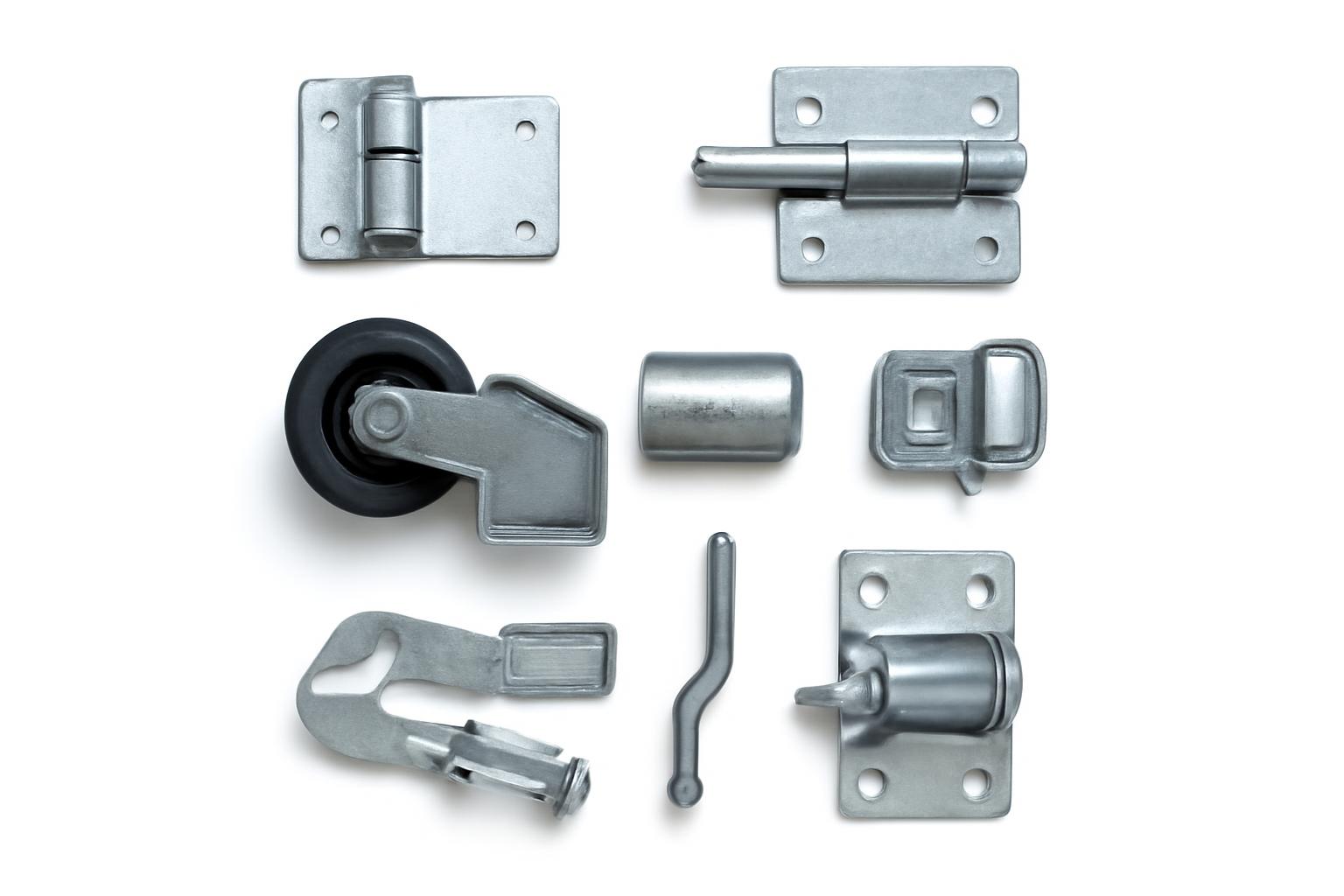
Choosing chain link gate hardware is primarily a compatibility problem. A hinge, latch, wheel, or roller can look correct yet still be wrong for the gate’s movement, tubing diameter, mounting geometry, or documented operating limits.
Begin by identifying how the gate moves. Then measure the actual outside diameters of the gate frame and posts—not merely their nominal pipe sizes. Record the opening, leaf dimensions, clearances, mounting method, gate weight, and expected frequency of use before comparing kits or individual components.
This guide focuses on component identification, dimensional screening, residential swing-gate hardware, double-drive arrangements, and introductory manual cantilever selection. Rolling, overhead, automated, unusually large, and safety-sensitive gates require documentation for the complete system; general catalog information is not enough to design or approve them.
Start With the Gate Type, Not the Hardware Catalog
Classify the gate by movement and number of leaves before shopping:
- Pedestrian walk gate or single swing gate: One leaf pivots from a hinge post.
- Double-drive gate: Two leaves pivot from opposing posts and meet in the center.
- Ground-supported rolling gate: The gate travels sideways on wheels or wheel carriers.
- Cantilever slide gate: Roller assemblies suspend and guide the gate without a supporting wheel in the opening.
- Overhead track-and-trolley gate: The gate travels on a dedicated overhead track system.
This decision determines the relevant component family. Retail catalogs commonly separate hardware sets, hinges, latches, closers, wheels, holdbacks, general components, cantilever hardware, and rolling-gate hardware. Some catalogs place overhead track-and-trolley equipment in its own category. American Fence & Supply’s catalog illustrates this category structure.
The major components perform different functions:
- Hinges establish the pivot for a swinging gate.
- Latches retain the gate in its closed position.
- Drop rods secure one leaf of a double gate at the ground.
- Wheels and rollers support, carry, or guide movement.
- Holdbacks retain a gate in an open position.
- Closers return a gate toward the closed position.
- Receivers capture the mating part of a latch.
- Brackets and U-bolts attach rollers, wheels, and related components to posts or frames.
A walk gate generally uses post-mounted and frame-mounted hinge halves plus a latch. A double-drive gate gives each leaf its own hinge arrangement and adds coordinated center-securing hardware. A manual cantilever system is more involved, commonly using roller posts, upper and lower rollers, mounting hardware, a latch post, and a receiver.
Separate essential hardware from optional functions. Closers, holdbacks, support wheels, roller covers, keyed locks, and mechanical code locks may be useful, but their appearance beside a gate in a catalog does not make them mandatory. Suitability depends on the complete gate design, dimensional fit, documented ratings, operating needs, and requirements applying to the site.
Track profiles, trolley assemblies, wheel arrangements, frames, stops, guides, and mounting details vary by system. Select these parts from documentation for the complete gate rather than assembling a system from category names alone.
Treat labels such as residential, commercial, industrial, and heavy duty as catalog descriptions, not standardized ratings. Unless the documentation states accepted dimensions, mounting method, maximum supported gate weight and leaf width, and any applicable duty or cycle rating, the label does not establish suitability.
Complete This Measurement Worksheet Before Ordering
Use a tape measure or caliper as appropriate and record everything in one place. Do not rely on an old receipt, an advertised gate width, or a nominal pipe label.
| Measurement or condition | Your result |
|---|---|
| Gate movement: swing, rolling, cantilever, or overhead | |
| Number of leaves | |
| Gate-frame shape: round or square | |
| Actual gate-frame outside diameter or dimensions | |
| Hinge-post shape and actual outside diameter | |
| Latch-post shape and actual outside diameter | |
| Clear opening between fixed surfaces | |
| Actual width of each gate leaf | |
| Gate height | |
| Swing direction: inward, outward, left, or right | |
| Clearance through the complete travel path | |
| Mounting surface: post, wall, masonry, steel, or other | |
| Existing wheel diameter and width, if applicable | |
| Existing roller diameter and bracket dimensions | |
| Gate weight from gate documentation, if available | |
| Expected operating frequency | |
| Existing bolt spacing and fastener diameter | |
| Existing bracket width, depth, and offset | |
| Existing attachment: bolt-on, clamp-on, wall-mounted, or welded |
Nominal size is not necessarily the measured diameter
Pipe and fence-framework descriptions can use a nominal size that differs from the actual outside diameter. One documented residential kit, for example, is intended for a nominal 2-1/2-inch post with a 2-3/8-inch actual outside diameter. It also requires a 1-3/8-inch gate-frame outside diameter. The kit specification shows why both measurements must be checked.
Measure round tubing directly across its widest point. For square tubing, record the outside width and depth. A nominal description may identify a general product family, but clamps and brackets must fit the physical tubing in front of you.
Post size and frame size are separate specifications. One hinge half may clamp around the post while the other attaches to the gate frame. A latch may mount on one tube diameter while closing around or against another. Matching only one side does not establish compatibility.
Opening width and leaf width are different
The clear opening is the usable distance between fixed posts, walls, or other boundaries. The leaf width is the physical width of the moving gate. A swing gate needs room for its hinge and latch hardware, so its leaf may be narrower than the opening it serves.
As residential planning examples, the Chain Link Fence Manufacturers Institute allows 3-3/4 inches for hinge and latch hardware on a single walk gate and 5-1/2 inches on a double-drive gate. Its example places a 32-1/4-inch leaf in a 36-inch opening. These are illustrative residential allowances, not universal clearances. CLFMI’s installation brochure provides the underlying examples.
For replacement hardware, also record:
- Center-to-center bolt spacing
- Fastener diameter
- Bracket width, depth, and offset
- Round or square tubing
- The side of the post or frame receiving the bracket
- Whether the component clamps, bolts, welds, or anchors to a wall
- Latch height and receiver position
- Distance between the hinge axis and gate frame
- Wheel axle and carrier dimensions
- Visible model numbers or manufacturer markings
Record gate weight from the original gate documentation or manufacturer when possible. Do not estimate a safe hardware capacity from appearance. Operating frequency should also be documented, but this guide does not supply a universal threshold separating residential, commercial, or high-cycle service. Compare both values with the selected manufacturer’s maximum supported gate weight, leaf width, and duty or cycle rating.
For a new installation, measure the delivered gate and hardware before setting posts permanently. Catalog drawings can assist planning, but the actual gate, hinges, rollers, latch, receivers, and brackets determine final geometry. Repeat the measurements before drilling irreversible holes or welding components.
Hardware Checklist for a Residential Walk or Single Swing Gate
A documented baseline hardware set for a residential chain-link walk gate consists of:
- Two male hinges, also called post hinges
- Two female hinges, also called frame hinges
- One fork-style latch
- Compatible carriage bolts
- Compatible nuts
The male hinges mount on the gate post, while the female hinges mount on the gate frame. In the cited residential procedure, the upper hinge is inverted to help resist the gate being lifted from its hinge pins, and the gate top is aligned with the adjoining fence before final tightening. CLFMI documents the component quantities, placement, hinge orientation, and alignment sequence.
A practical installation sequence is:
- Confirm the opening and actual frame and post dimensions.
- Verify that both halves of each hinge fit their intended tubing.
- Position the male hinges on the hinge post.
- Attach the female hinges to the gate frame.
- Hang the gate on the post hinges.
- Adjust the hinge positions until the gate travels through its full intended swing.
- Align the gate top with the adjoining fence.
- Position the latch so it engages without lifting or forcing the gate.
- Tighten the hardware under the selected product’s instructions.
- Operate the gate repeatedly and recheck alignment.
Retail catalogs list numerous hinge formats, including:
- Separate male and female fittings
- Bulldog hinges
- Barrel hinges
- Strap hinges
- Bolt-on hinges
- Weld-on hinges
- Adjustable hinges
- Self-closing hinges
- Wall-mount hinges
Compare these by documented fit, function, and mounting method. Bolt-on and clamp-on products avoid welding but still require the specified geometry and fasteners. Adjustable hinges provide only the adjustment range stated by their manufacturer. Self-closing hinges add a return mechanism that must be installed, adjusted, and tested under their own instructions.
Do not infer weight capacity, service life, or safety performance from a hinge’s shape or marketing name. Catalog listings confirm that these formats exist, but the product’s technical documentation must establish what gate it can support.
A complete kit can be convenient when every component matches the installation. One documented residential kit groups two male hinges, two female hinges, a fork latch, carriage bolts, and nuts, and is listed as pressed steel with a hot-dip galvanized finish. The seller describes these as “typical” contents, so the current packing list should be verified rather than treated as guaranteed. The retailer’s kit page lists its typical contents, material, finish, and padlock provision.
The listed fork latch accepts a standard padlock. That means a compatible lock can be attached; it does not establish a tested security rating for the latch, gate, or complete enclosure.
Double-Drive Gates: Hinges, Center Latches, and Drop Rods
A double-drive gate has two swinging leaves, normally hung from opposing posts. Each leaf needs its own hinge arrangement, and the gate needs a coordinated system for controlling how the leaves meet and remain closed.
In CLFMI’s bounded residential material example, the double-drive gate uses four male and four female hinges. That count should not be converted into a universal design rule for unusually tall, wide, heavy, or frequently operated gates. Those applications require product-specific capacities.
Two center components are commonly involved:
- A center latch joins, captures, or retains the two leaves.
- A drop rod holds one leaf at the ground so the other can close against a stable center point.
The exact arrangement varies. The cited residential material and installation language is not fully consistent about fork-latch use on double gates: one passage associates the fork latch with walk gates, while another identifies a center fork latch for a double gate. Confirm whether the selected system requires a center latch, receiver, drop rod, ground socket, stop, or a combination of these.
Catalogs also list double-gate latches, fulcrum-style latches, residential and industrial drop rods, latch receivers, holdbacks, and gate stops. One retailer-listed fulcrum latch is offered for 1-5/8-inch and 2-inch gate frames, demonstrating why the accepted frame diameter must be checked even when the product name appears correct. Hoover Fence’s catalog lists those frame-size options.
A drop rod’s receiving point must remain aligned with the rod when the gate is closed. Because site and surface conditions vary, this guide cannot prescribe a universal socket, rod length, or footing detail. Use the component instructions and the site-specific gate design.
Support wheels and gate-helper products are available for swing gates, but they are not automatic requirements. The available evidence does not establish a universal leaf width or weight at which a wheel becomes mandatory. If one is being considered, verify the accepted frame diameter, wheel dimensions, load rating, mounting geometry, and intended travel surface. Displayed wheel assemblies, for example, are listed for 1-5/8-inch or 2-inch gate frames rather than every tubing size. First Fence’s catalog shows those frame-specific wheel assemblies.
Before final tightening, bring both leaves to their natural closed positions without forcing them. Confirm that:
- Their top rails meet at the intended height.
- The center gap is consistent.
- Neither leaf must be lifted to engage the latch.
- The drop rod enters its receiver cleanly.
- The secured leaf provides the intended stop for the other.
- Both leaves can complete their intended travel without interference.
If the leaves do not meet naturally, recheck post, hinge, leaf, and receiver geometry instead of relocating the latch merely to conceal the misalignment.
Cantilever, Rolling, and Overhead Gates Need System-Specific Parts
“Sliding gate” is a broad shopping term rather than a single hardware design:
- A cantilever gate is suspended and guided by roller assemblies near the opening.
- A rolling gate travels on ground-supporting wheels or wheel carriers.
- An overhead gate uses a track-and-trolley arrangement above the gate.
These systems are not interchangeable simply because they all move sideways.
Cantilever gate component map
A typical manual cantilever arrangement described in the supplied installation material uses:
- Two roller posts
- One latch post
- One bottom roller on each roller post
- Upper guide rollers
- U-bolts or other specified mounting hardware
- Roller covers
- A cantilever latch
- A receiver or mating latch component
In that arrangement, the bottom rollers are mounted one to each roller post and leveled to each other. The upper rollers guide the top rail rather than clamping it tightly. The cited configuration recommends 1/4- to 1/2-inch clearance between a top roller and the top gate rail; that is system-specific guidance, not a universal setting for all cantilever products. Hoover Fence’s cantilever guide describes the layout and stated clearance.
The same arrangement places the fork or receiver on the latch post and the smaller mating component on the gate’s leading edge. Its latch can accept a padlock when closed, but that feature does not establish resistance to forced entry.
Cantilever rollers are listed in different sizes and materials, including steel and nylon. Product names and materials alone do not prove that one roller is quieter, stronger, safer, or longer-lasting than another. Match the roller to the documented post diameter, gate rail, bracket arrangement, and supported load.
The cited seller recommends roller covers as a pinch-point precaution for its described installation. Treat that as a product-specific precaution, not proof that a particular cover satisfies every applicable requirement or removes all hazards.
Rolling and overhead hardware
Rolling-gate catalogs list wheel carriers, rear-wheel assemblies, double-wheel assemblies, guide rollers, stops, brackets, and kits. One displayed pneumatic double-wheel carrier is listed for 1-5/8-inch or 2-inch frames and 8- to 10-inch wheels. Other collections show internal truck assemblies, truck brackets, bottom guide rollers, swivel rollers, and gate-helper products. These examples establish product variety, not a universal rolling-gate design. Hoover Fence’s catalog provides the listed carrier compatibility example.
The same limitation applies to overhead systems. Available catalogs establish that overhead track-and-trolley hardware exists, but they do not provide a complete bill of materials or installation procedure suitable for every gate.
Measure delivered wheels, carriers, rollers, brackets, tracks, and tubing before final post placement. If the gate will be connected to an automated operator, do not adapt manual rolling or cantilever instructions. Use the current documentation for the operator and complete gate system, along with requirements identified by the authority governing the site.
Choose Materials, Finishes, and Mounting Styles Without Relying on Marketing Labels
Chain-link gate hardware is listed in steel, stainless steel, aluminum, polymer, and nylon. Catalog finishes include galvanized, hot-dip galvanized, pre-galvanized, zinc, mill, black, brown, green, white, silver, and other coated options.
Those descriptions can support comparisons of:
- Dimensional compatibility
- General appearance
- Available colors
- Stated base material
- Stated finish
- Mounting method
- Availability within a product family
- Visual coordination with the gate
They do not, by themselves, establish corrosion lifespan, salt resistance, load capacity, maintenance interval, or service life. A “galvanized” description, for example, does not necessarily disclose coating thickness, fabrication sequence, or expected performance in a particular environment.
A black, green, brown, or white gate may call for visually matching hardware. Color alone does not prove that the gate and hardware use the same coating process or offer equivalent corrosion performance.
Mounting style has practical consequences:
- Bolt-on hardware uses prepared holes or brackets and requires the specified spacing and fasteners.
- Clamp-on hardware wraps around tubing and must match its shape and actual outside diameter.
- Weld-on hardware requires suitable equipment and skill, as well as attention to any affected coating.
- Wall-mount hardware requires a suitable mounting surface and compatible anchors.
- Strap and barrel hinges describe physical formats, but their accepted geometry and ratings remain product-specific.
- Self-closing hardware includes a return mechanism governed by its own installation and adjustment instructions.
Retail collections list bulldog, barrel, strap, bolt-on, weld-on, adjustable, and self-closing configurations. Their catalog labels do not establish comparable capacities. FenceSupplyCo’s collection illustrates the range of listed hinge formats.
For coastal, chemical, deicing-salt, or persistently wet environments, request product-specific guidance from the hardware manufacturer. The supplied evidence does not establish safe or durable combinations of galvanized steel, stainless steel, aluminum, and coated components in every environment.
Before buying, confirm these items on the individual product page or technical sheet:
- Base material
- Finish specification
- Accepted tubing dimensions
- Included fasteners
- Mounting method
If any are missing, ask the seller or manufacturer rather than filling the gap with a marketing label.
Installation and Alignment Checkpoints
Before excavation or permanent installation, ask the relevant local authority about permits, setbacks, property boundaries, footing rules, and other site requirements. Arrange for underground utilities to be located before digging. The cited cantilever guide likewise directs installers to check permits and restrictions, confirm setbacks, and contact 811 before excavation. Its preparation guidance also emphasizes measuring the delivered system before final layout.
For a walk or single swing gate:
- Reconfirm the clear opening and actual tubing dimensions.
- Verify that each hinge half and latch component fits its intended tubing.
- Mount the post hinges.
- Attach the frame hinges.
- Hang the gate.
- Orient the upper hinge as required by the applicable system.
- Align the gate top with the adjoining fence.
- Move the gate through its complete intended swing.
- Adjust the latch so it engages without lifting or forcing the leaf.
- Complete final tightening under the product instructions.
For a manual cantilever gate, the central checkpoints are:
- Roller and latch posts positioned for the delivered system
- Posts aligned as required by the system instructions
- Site-appropriate footings determined under applicable local requirements
- Bottom rollers level with each other in the cited arrangement
- Upper rollers adjusted to the specified clearance
- Free travel through the complete opening
- Final alignment between the gate-mounted latch component and post-mounted receiver
- Product-specified covers or guards installed where required
Generic guidance cannot provide universal bolt torque, fastener grade, footing dimensions, curing requirements, or maximum gate weight. Those values depend on the selected hardware, complete gate system, ground conditions, and applicable requirements.
After installation or adjustment, perform a limited functional check without treating this article as a substitute for the manufacturer’s commissioning procedure:
- Move the gate through its complete intended travel.
- Check for visible interference, dragging, or binding.
- Confirm that the latch engages without lifting or forcing the gate.
- Verify that drop rods and receivers align.
- Check that installed fasteners remain seated during operation.
- Confirm that wheels remain positioned on their intended travel surface.
- Recheck alignment in both open and closed positions.
Self-closing and automated equipment must be adjusted and tested under the current manufacturer’s instructions. Work involving automation, welding, significant structural movement, or unusually large leaves falls outside the residential installation scope of this guide.
Troubleshoot the Geometry Before Replacing Parts
A latch that misses its receiver is not necessarily defective, and a dragging gate does not automatically need a support wheel. Begin with visible condition and dimensional fit rather than assuming a particular repair.
The following table is a limited inspection aid, not a diagnosis or repair procedure:
| Symptom | Initial visual or dimensional checks |
|---|---|
| Gate misses the latch | Post position, moved hinge fittings, visible frame sag, leaf height, center gap, latch and receiver alignment |
| Gate drags | Hinge position, visible frame distortion, support-wheel position if fitted, obvious travel-path obstruction |
| Gate binds or has limited swing | Hinge-axis alignment, available clearance, displaced fittings, interference with the post or fence |
| Gate appears vulnerable to lift-off | Presence, attachment, and orientation of the upper hinge |
| Double leaves do not meet | Relative leaf height, center gap, hinge position, drop-rod engagement, latch geometry |
| Cantilever gate rolls unevenly | Roller-post position, bottom-roller level, specified upper-roller clearance, visible roller damage, loose mounting hardware |
| Wheel wobbles | Carrier fit, accepted frame diameter, axle and wheel dimensions, visibly loose or damaged parts |
| Hardware rotates around tubing | Actual tube diameter, clamp fit, bracket seating, installed fasteners |
For a gate that misses the latch, compare its natural closed position with the receiver. Check visible post and hinge position, the gate’s height, and the center gap before relocating hardware. Moving the latch may conceal a larger alignment problem.
For dragging, determine whether the leaf or supporting hardware has visibly moved and whether an obvious obstruction is present. If the gate uses a support wheel, verify that its carrier still fits the frame and that the wheel remains on its intended path. Do not add a wheel solely because dragging is present.
For binding, check whether the upper and lower hinges share a consistent pivot axis and whether brackets or fittings interfere with the post or fence. Do not guess at torque values or loosen structural fasteners beyond the applicable instructions.
For lift-off concerns, verify that the upper hinge is present, securely attached, and oriented under the selected system’s instructions. The inverted-upper-hinge arrangement described earlier applies to the cited residential configuration; it is not a universal substitute for product-specific installation details.
For uneven cantilever movement, visually check roller-post position, lower-roller level, upper-roller clearance, mounting hardware, and roller condition before assuming the latch is creating resistance.
Wheel wobble calls for dimensional verification. Confirm that the carrier accepts the measured frame diameter and installed wheel dimensions. Visual similarity between an existing component and a replacement listing does not establish interchangeability.
This guide cannot determine whether an unstable gate or a gate with failed structural components remains safe to operate. Do not improvise a structural repair, lubricant, torque setting, or replacement interval without the applicable documentation. An automated gate behaving unpredictably requires the current operator and gate-system instructions rather than manual-gate troubleshooting.
The purchase rule remains the same: replacement hardware must match the measured geometry and documented rating. Looking like the old part is not enough.
Final Buying Checklist and Realistic Price Expectations
Before checkout, verify every applicable item:
- [ ] Gate type and method of movement
- [ ] Number of leaves
- [ ] Actual gate-frame outside diameter or square dimensions
- [ ] Actual hinge-post outside diameter
- [ ] Actual latch-post outside diameter
- [ ] Clear opening
- [ ] Actual leaf width and height
- [ ] Swing or slide direction
- [ ] Required operating clearance
- [ ] Mounting method
- [ ] Bolt spacing and bracket geometry
- [ ] Gate weight from available documentation
- [ ] Intended operating frequency
- [ ] Manufacturer’s maximum supported gate weight
- [ ] Manufacturer’s maximum supported leaf width
- [ ] Manufacturer’s stated duty or cycle rating, if applicable
- [ ] Base material and finish
- [ ] Latch function
- [ ] Padlock, key, or code requirement
- [ ] Wheel or roller diameter
- [ ] Accepted post and frame dimensions
- [ ] Included fasteners
- [ ] Required fastener specifications
- [ ] Replacement-part availability
- [ ] Compatibility with the complete gate system
Choose between a kit and individual components according to dimensional fit and package completeness. A kit is convenient only when every included part fits. Individual components may be more appropriate when replacing a single fitting, working with nonstandard tubing, retaining an existing latch, or combining different mounting methods.
Prices vary widely because the products perform different jobs. At the time captured in the supplied retailer material, one residential walk-gate kit was displayed at $18.99. That figure is a changeable retailer snapshot, not an expected or recommended price, and current price, stock, shipping, and contents must be checked before purchase.
The captured Hoover Fence catalog showed a pressed-steel hinge at $17.27 and a mechanical code gate-lock kit at $780.92. These products serve different functions, so the price spread is not a quality comparison.
A separate retailer catalog displayed a residential double-wheel assembly at $49.36, while small latch fittings were listed for substantially less. First Fence’s listings illustrate that category-level price difference.
Specialized closing hardware can also cost hundreds: one captured self-closing hinge kit was displayed at $251.13. Prices and stock can change, and the individual product documentation must still establish compatibility. FenceSupplyCo’s collection supplied that retailer-listed example.
A higher price does not prove that a component is better, and a lower price does not prove that it is inadequate. The products may differ in function, frame and post fit, mounting method, adjustment features, access-control function, and supported gate system.
Verify current price, availability, shipping cost, exact package contents, and specifications on the individual product page. Marketplace result counts, sponsored placement, star ratings, discount labels, and terms such as “professional” or “heavy duty” do not establish compatibility.
When information is missing, ask the seller or manufacturer:
- What actual outside-diameter range does the fitting accept?
- What maximum gate weight and leaf width does it support?
- Is a duty or cycle rating stated?
- What mounting geometry is required?
- Which fastener type and grade are specified?
- What is the base material and finish specification?
- Are all mounting fasteners included?
- Are replacement bearings, rollers, springs, or latch parts available?
- Is the component approved by its manufacturer for the intended gate system?
- Does installation require welding or coating repair?
- Which current technical document controls installation and adjustment?
The action plan is straightforward: classify the gate, record every actual diameter and opening dimension, identify the correct component family, and verify fit, ratings, mounting geometry, and included fasteners. Catalog labels and low prices cannot compensate for a dimensional mismatch.
For a large, automated, structurally unstable, or safety-sensitive gate, use current manufacturer documentation and an appropriately qualified installer rather than extending basic residential guidance beyond its supported scope. Do not order until every critical dimension and rating has a documented match.
Frequently Asked Questions
What hardware is normally included in a residential chain-link walk-gate kit?
A typical documented residential kit contains matched post and frame hinges, a fork-style latch, carriage bolts, and nuts. Because sellers may describe this only as a typical packing list, confirm the current contents before ordering.
The kit must match both the gate frame and the hinge post. A complete package is not useful if even one clamp or bracket is sized for different tubing.
How much space should I allow between chain-link gate posts for hinges and a latch?
Do not use a universal gap. Determine the required post spacing from the delivered leaf and selected hinge and latch geometry.
Residential planning examples can help with preliminary layout, but they do not replace measurement of the actual gate and hardware before posts are set permanently.
Why do nominal post sizes and actual outside diameters differ?
A nominal size is a trade designation and may not equal the tube’s measured outside diameter. Hardware clamps and brackets fit the physical tube, so measure the outside diameter directly and compare it with the product’s accepted dimensions.
Record the gate-frame and post dimensions separately. A hinge or latch may need to match both.
Can a chain-link gate latch accept a padlock?
Some fork, butterfly-style, and cantilever latches include a padlock provision; others do not. Check the individual product rather than assuming the feature is standard.
A padlock hole or loop establishes only that a compatible lock can be attached. It does not prove a tested level of security, code compliance, or resistance to forced entry.
What is the difference between rolling and cantilever gate hardware?
A rolling gate is supported by wheels or wheel-carrier assemblies as it moves sideways. Its system may include rear wheels, double-wheel carriers, guide rollers, stops, and related brackets.
A cantilever gate is suspended and guided by rollers near the opening. It commonly uses roller posts, upper and lower rollers, mounting hardware, a latch post, and a receiver rather than relying on the same ground-wheel arrangement across the opening.
Both differ from an overhead gate, which uses a track-and-trolley system. Each requires its own dimensions, components, ratings, and installation documentation.