
How to Plan a Chain-Link Fence With a Barbed-Wire Topping
Site permission and measured framework come first, followed by location-specific arms, structural assessment where needed and a complete installed quote.
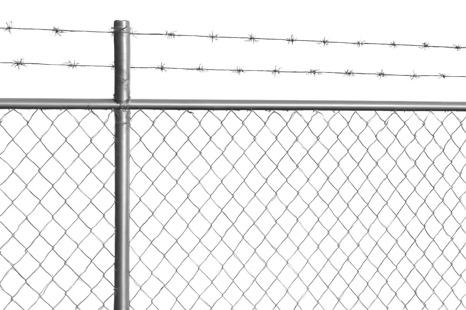
A chain-link fence with barbed wire is a component-based perimeter system, not one combined product. Chain-link fabric and framework form the main fence; separate arms support tensioned barbed-wire strands above it.
That distinction affects purchasing and planning. Arms must match the measured posts and top rail. Terminal and corner assemblies must accommodate strand terminations and changes in direction. Gates need configuration-specific hardware and operating clearance. An existing fence should not be assumed capable of carrying the added system simply because a retrofit arm fits its posts.
This guide is therefore a purchasing and pre-installation planning overview—not an installation specification, structural assessment, code interpretation, or complete job-safety plan. Site-specific permission must come from the relevant authorities, structural questions from a qualified professional, and installation requirements from the selected manufacturers and project documents.
The practical sequence is to define the perimeter objective, ask the appropriate authorities whether the proposed configuration is allowed, document the framework, select location-specific fittings, refer uncertain structural conditions for professional assessment, and price the entire installation.
What a chain-link fence with barbed wire actually includes
The basic assembly consists of chain-link fabric stretched across a post-and-rail framework, with separate support arms and barbed-wire strands above it. Retail catalogs commonly classify fabric, framework, fittings, barbed wire, gates, and related hardware as separate product groups.
This differs from a standalone agricultural barbed-wire fence. In a livestock-style fence, the barbed-wire strands are the primary barrier and use their own line posts, end posts, braces, spacing, and fastening system. Dimensions and installation practices for that kind of fence should not automatically be transferred to an overhead chain-link topping.
A complete chain link fencing barbed wire fence plan may include:
- Chain-link fabric: The woven mesh forming the main fence surface.
- Line posts: Intermediate posts supporting the fence between structural endpoints.
- Terminal posts: End posts where fabric and overhead strands begin or terminate.
- Corner posts: Structural posts where the fence changes direction.
- Gate posts: Posts selected around gate loads, movement, and clearances.
- Top rail: Horizontal framework connecting posts and supporting the top of the fabric.
- Brace rails and bands: Components used at terminal, corner, brace, and gate assemblies.
- Bottom tension wire or another bottom attachment: Controls the lower edge of the fabric.
- Tension bars and bands: Secure chain-link fabric at terminal locations.
- Fabric ties or clips: Attach fabric to posts, rails, and tension components.
- Barbed-wire support arms: Vertical, angled, double, or retrofit fittings mounted above posts or gate members.
- Terminal arms, bands, or approved terminal fittings: Provide termination points for the overhead strands.
- Barbed wire: Separate wire runs supported above the fence.
- Arm slots, shaped cuts, ties, or clips: Retain strands at intermediate locations.
- Gates and gate-topping hardware: Components selected for the gate type and travel path.
- Gripping and tensioning equipment: Tools used to control and tension each run.
- Fasteners and finish-repair materials: Bolts, bands, clamps, ties, clips, and compatible coating products.
Line and terminal locations are not interchangeable. A line-post arm supports wire between endpoints, while a terminal assembly receives the strand termination. Corners redirect the runs, and gate posts or gate frames introduce movement and clearance requirements.
Some arms fit over line posts like caps and allow the top rail to pass through them. Others bolt, clamp, or band onto compatible framework. A specialty retailer’s catalog lists vertical, angled, V-shaped, line-post, corner-post, gate, bolt-on, and clamp-on configurations, including products described for three or six strands. Those are catalog examples rather than universal capacities or designs (barbed-wire arm product catalog).
A listing that depicts or markets a high-security chain-link configuration may still exclude the posts, gates, topping wire, and hardware. One manufacturer expressly identifies gates, posts, wire, and related hardware as separately supplied alongside its chain-link fabric (manufacturer’s component listing). Every proposal should therefore be checked as a bill of materials rather than treated as complete because its photographs show a finished fence.
Barbed wire is also only one part of a perimeter plan. The result depends on the framework, mesh, gates, locks or access controls, sightlines, lighting, and monitoring. A topping creates a visible climbing obstacle, but the available evidence does not establish that it prevents entry or gives the perimeter a quantified security rating.
Decide whether this configuration fits the site and objective
Begin with the actual objective. Possible goals include:
- Marking a boundary
- Containing authorized activity or certain animals
- Discouraging casual climbing
- Reducing opportunistic access or theft
- Controlling entry to an operational area
- Establishing a visible industrial or agricultural perimeter
These are not equivalent requirements. A configuration used primarily for boundary marking may be poorly matched to a busy equipment yard. Conversely, a design proposed for a controlled industrial site may create unacceptable exposure along a residential or pedestrian-facing boundary.
Chain-link fabric preserves airflow and sightlines. Ordinary mesh can nevertheless be climbed or cut, and seller descriptions do not establish a measured level of security. Evaluate the fence as one part of a boundary and delay system rather than assuming it will prevent access.
Suppliers market barbed-wire-topped chain link for industrial, transportation, agricultural, military, mining, livestock, and other controlled-access settings. These examples show where products are offered; they do not establish that the configuration is lawful, suitable, or adequately designed for every property in those categories.
Residential properties, schools, sports areas, roadsides, and publicly accessible boundaries warrant especially careful site-specific review. The available evidence does not determine where barbed wire is permitted. Ask the responsible authorities and other relevant parties which of the following questions apply:
- Does zoning or the building code restrict barbed wire at this property?
- Is there a fence-height limit?
- Is a permit, plan review, or other approval required?
- What setbacks apply, and how will the property line be verified?
- Do road, intersection, or sight-distance rules affect the fence?
- Are there utility easements or underground-service requirements?
- Do HOA documents or deed restrictions address the design?
- Are warning signs required?
- Does the property insurer impose conditions or exclusions?
- What fire, emergency, and maintenance access must remain available?
- What gate egress or emergency-opening requirements apply?
- May an arm or strand project toward a boundary, sidewalk, road, easement, or right-of-way?
A fencing contractor recommends checking local zoning and HOA restrictions before installing chain link, but that general guidance does not answer any property-specific barbed-wire question. Permission should be confirmed with the authority responsible for the site rather than inferred from a contractor article (contractor planning guidance).
Physical orientation is not legal approval. Some angled arms can be installed facing either side of a fence, but this establishes only what the fitting can physically do. It does not establish that an outward projection is permitted or appropriately located.
Map who may approach the fence during both normal and unusual conditions:
- Children and pedestrians
- Customers, visitors, or tenants
- Pets and livestock
- Wildlife
- Grounds and maintenance personnel
- Delivery drivers
- Utility crews
- Firefighters and other emergency responders
Also consider how workers will trim vegetation, repair fabric, service lights, clear debris, and operate gates without contacting the topping.
If the objective is climb deterrence or improved perimeter awareness, compare the proposed topping with other measures such as greater fence height, smaller mesh, stronger gates, improved locks, access control, lighting, alarms, or surveillance. The evidence does not establish one universally superior solution. Selection depends on the site, threat, public exposure, operations, and applicable requirements.
Choose the correct barbed-wire arm and strand configuration
Arm selection begins with position, mounting method, and measured compatibility—not appearance. A fitting intended for an intermediate line post may be unsuitable at a terminal, corner, or moving gate.
| Arm or fitting style | Position and function | Common mounting approach in available catalogs | Capacity shown in catalog examples | Details to confirm |
|---|---|---|---|---|
| Straight or vertical arm | Holds strands above the post line without a side projection | Slip-on, cap-style, bolt-on, or system-specific | Three- and six-strand versions are listed | Post outside diameter, rail passage, slot arrangement, height, finish |
| 45-degree arm | Projects strands to one side of the post line | Often slips over a line post before the top rail is installed | Documented three-strand versions; other products vary | Post and rail outside diameters, orientation, boundary clearance |
| V-shaped or double arm | Places strands on both sides of the post line | Post-top or assembly-specific fitting | Six-strand examples, commonly divided between both sides | Post compatibility, overall width, public exposure, terminal treatment |
| Line-post arm | Supports strands between structural endpoints | Slip-on, bolt-on, clamp-on, or blade-and-band assembly | Three- and six-strand examples | Line-post and rail fit; it is not automatically a terminal anchor |
| Corner-post arm | Carries or guides topping through a change in direction | Corner-specific cap, extension, or attached fitting | Product-dependent, including six-strand listings | Bracing, turn geometry, anchorage, strand continuity |
| Gate arm | Extends topping across or beside a gate | Gate-frame, gate-post, or cantilever-upright attachment | Product-dependent | Gate travel, hinges, latches, rollers, operators, vehicles, overhead clearance |
| Universal blade | Adaptable extension used with separate attachment hardware | Commonly installed with brace bands | Three-strand examples | Required bands and bolts, included hardware, rotation resistance |
| Bolt-on retrofit arm | Adds an arm without removing every section of top rail | Bolted around or through compatible framework | Product-dependent | Member size, approved bolt placement, drilling restrictions, coating damage |
| Clamp-on retrofit arm | Clamps around a rail or post | Two-part or bracket-style clamp | Product-dependent | Actual outside diameter, clamp requirements, member condition, finish compatibility |
The mounting approaches and capacities above are product-catalog examples, not universal specifications. The selected manufacturer’s documentation controls.
Catalogs include both three- and six-strand products, but neither count is universally sufficient. Strand count alone does not establish a security level.
One product family illustrates how specific the compatibility requirements can be. Its 45-degree arms slip over intermediate posts, accept a 1-5/8-inch top rail, and retain three strands in Z-shaped cuts. The listed post outside-diameter options are 1-5/8, 2, 2-1/2, and 3 inches (45-degree arm specifications). These dimensions describe that product family, not all angled arms.
A straight arm keeps the topping over the post line. A single angled arm projects it to one side, while a V-shaped arm places wire on both sides and creates a wider overhead assembly. Selection should account for the approved boundary, public contact, gate travel, maintenance access, and applicable restrictions—not merely the number of slots.
Terminal and corner treatment should be selected with the line-post arms. Depending on the system, strands may terminate on purpose-built terminal arms or compatible band arrangements. A change of direction at a corner needs a corner and termination strategy; a standard line-post arm should not be assumed to perform those functions.
Gate hardware requires a separate review. Swing gates trace an arc. Slide gates need a clear travel path. Cantilever gates move past support posts, rollers, and other hardware. An arm that fits a gate upright may still interfere with the gate posts, operator, latch, vehicles, adjacent fencing, or overhead objects.
Package contents also vary. For example, one catalog states that a three-wire universal retrofit blade requires two additional brace bands that are not included (retrofit blade and arm listings). Other products may omit bolts, clips, terminal hardware, or coating-repair materials. “Universal” should be read as a product description, not permission to skip measurement and component verification.
Measure compatibility before ordering hardware
Do not order arms from a verbal description such as “two-inch post” or “standard commercial rail.” Measure the installed framework and compare the results with the exact manufacturer specification.
Use a worksheet for every distinct fence condition:
| Field | Measurement or decision |
|---|---|
| Fence segment or post identifier | |
| Post location | Line / terminal / corner / gate / brace |
| Measured post outside diameter | |
| Measured top-rail outside diameter | |
| Existing cap or fitting | |
| Proposed arm type | |
| Mounting method | Slip-on / bolt-on / clamp-on / banded |
| Orientation | Vertical / inward / outward / double |
| Number of strands | |
| Framework finish | |
| Arm and fastener finish | |
| Terminal connection | |
| Corner treatment | |
| Required bands, bolts, ties, or clips | |
| Gate and vehicle clearance | |
| Manufacturer specification verified | Yes / No |
| Components included in quoted price |
Measure with a tool suitable for outside diameter and check multiple locations. A fence may contain replacement posts, sleeves, mixed framework, damaged rail, or undocumented repairs.
The documented 45-degree example accepts four listed post outside diameters while retaining a 1-5/8-inch top-rail requirement. Other catalog products are offered for different post and rail dimensions. A size taken from one product page should therefore never be generalized to a different line arm, corner fitting, terminal assembly, or gate attachment.
Mounting sequence also matters:
- Slip-on arms commonly form part of the post-cap and top-rail assembly. Retrofitting them may require top-rail disassembly or modification.
- Bolt-on arms may avoid full rail removal but still must match the post or gate member and the manufacturer’s attachment method.
- Clamp-on arms address a different access problem and depend on the actual diameter and condition of the clamped member.
- Band-mounted blades require compatible bands and bolts, plus an attachment arrangement that prevents unintended movement.
Before ordering, verify the finishes of the arms, posts, wire, bands, and fasteners. Confirm the manufacturer’s requirements for coating repair where drilling, cutting, or abrasion is permitted. Also identify the necessary terminal fittings, corner hardware, slots or clips, fasteners, and separately supplied parts.
Stop and recheck—or refer the condition to the manufacturer, installer, or project professional—if:
- A measurement falls between listed sizes.
- Different segments use different framework dimensions.
- Pipe is significantly corroded, crushed, oval, sleeved, bent, or patched.
- An arm will not seat fully or its rail opening is misaligned.
- The slots or clips do not match the chosen retention method.
- An arm would interfere with a gate, operator, roof, sign, light, or utility.
- The product documentation provides no clear dimensional specification.
- Required terminal fittings, bands, bolts, or clips cannot be identified.
- The proposed projection could cross the approved boundary.
A nearly compatible fitting is not compatible. Do not depend on forced assembly, improvised shims, unapproved drilling, or field bending unless the product manufacturer and project professional expressly allow the method.
Assess whether an existing chain-link fence can be retrofitted
A retrofit and a new installation follow different paths. New construction allows the framework, footings, braces, gates, and arms to be designed together. A retrofit preserves existing framework only if its condition and capacity are suitable for the proposed work.
Inspect the affected perimeter for warning signs that require correction or referral:
- Corroded, perforated, bent, or patched posts
- Leaning posts or visible movement
- Cracked, heaved, displaced, or exposed footings
- Missing or visibly damaged terminal and corner bracing
- Loose, separated, or badly spliced top rail
- Damaged fabric ties, tension bars, bands, or other attachments
- Bent post tops or deformed caps
- Sleeves, welds, patches, or undocumented repairs
- Gates that already sag, rub, or lose alignment
- Insufficient clearance around swing, slide, or cantilever gates
- Slopes or grade changes that complicate strand alignment
Visible movement is a stop-and-refer warning, not a structural test. Likewise, the absence of obvious corrosion, movement, or cracking does not prove that a post, footing, brace, or terminal assembly has adequate capacity.
Terminal locations receive strand terminations, corners change the direction of the runs, and gates introduce configuration-specific conditions. The evidence supplied here does not provide engineering criteria for determining allowable capacity.
Commercial supplier guidance says arms may be added when existing posts are sound, securely anchored, and strong enough. The supplier does not define engineering thresholds or establish that a visual inspection can prove adequacy (commercial retrofit guidance).
Bolt-on and clamp-on products solve an attachment problem.
Treat uncertain capacity as a reason to seek a site-specific professional assessment, particularly where the project has:
- Long uninterrupted runs
- Multiple corners or significant elevation changes
- Large swing, slide, or cantilever gates
- Steep slopes
- Moving posts or cracked concrete
- Significant public exposure
- Privacy slats or screening
- Unusual wind, soil, drainage, or corrosion conditions
- Mixed or undocumented framework
- Serious operational consequences if a section fails
These are referral considerations, not engineering thresholds. The evidence does not quantify how long, steep, exposed, or deteriorated a fence must be before reinforcement is required.
Stop work if a post shifts, a terminal leans, an arm rotates, a footing cracks, hardware deforms, a rail joint moves, or a gate loses clearance during setup or tensioning. If wire is already under tension, control access to the area and obtain qualified assistance rather than improvising a release or correction.
Understand the installation sequence without overlooking the hazards
Readers without appropriate training, tools, and site controls should use a qualified fence installer. The sequence below is for project planning and quote review only; it does not replace manufacturer instructions, an approved project specification, or a job-specific safety plan.
At a high level, the work proceeds as follows:
- Verify the approved fence line, height, arm orientation, gate layout, and boundary clearance.
- Establish suitable posts, footings, terminal bracing, corner assemblies, rails, and gates.
- Install compatible arms in their correct locations and orientation.
- Stretch and attach the chain-link fabric.
- Prepare the approved terminal arms, bands, or other strand connections.
- Anchor and tension each barbed-wire run using the selected system and equipment.
- Seat or fasten the strands in the intermediate-arm slots, ties, or clips.
- Inspect posts, arms, terminations, gates, fabric attachments, loose ends, and clearances.
The cited product instructions for slip-on overhead arms place the arms and top rail first, chain-link fabric stretching next, and overhead wire stretching last. That ordering applies to the documented product arrangement and should not be generalized where another manufacturer specifies a different sequence.
Terminal attachment also varies. Some systems use special terminal arms; others use compatible bands on extended terminal posts. Do not assume that a line-arm slot, ordinary cap, miscellaneous clamp, or improvised knot can serve as a termination.
The available retailer instructions warn against overtensioning and acknowledge that some sag may remain, but they provide no universal numerical tension value. If a post moves, an arm twists, a fitting deforms, or a terminal assembly leans, stop rather than increasing the pull.
Published strand-order guidance must be read in context. One overhead-arm supplier recommends working from the top down to reduce tangling and overlap. A separate bottom-up recommendation applies to a standalone agricultural barbed-wire fence, not an overhead chain-link topping. It should not automatically be transferred to this assembly.
A retailer’s chain-link barbed-wire guide warns that the material can unravel, tangle, cut, and injure, and calls for gloves, safety glasses, and continuous control of the wire (barbed-wire handling guidance). Another supplier lists thick gloves, safety glasses, wire-carrying equipment, cutters, grippers, clamps, and stretching tools for overhead-arm work.
For planning purposes, the work package should therefore address:
- Thick or puncture-resistant gloves appropriate to the task
- Safety glasses
- Sturdy footwear and protective clothing
- Equipment intended to carry, grip, cut, and tension the selected wire
- Controlled opening and unrolling of coils
- Continuous control of loose wire ends
- Prompt collection of sharp scraps and binding material
- Restricted access to the immediate work area
- A stop-work response if the wire begins to recoil or tangle uncontrollably
Protective clothing and cleanup guidance also appear in a standalone-fence supplier guide, but its construction dimensions and strand sequence do not apply automatically to an overhead topping (standalone-fence safety guidance).
Working with barbed wire requires caution, especially when working at height How to Install Barbed Wire Onto a Barbed Wire Arm | Chain Link Fittings. The available evidence supplies no complete hazard analysis, universal safe tension range, or engineering acceptance criteria. Those limits should be established through the selected manufacturers’ instructions, applicable workplace requirements, approved project documents, and qualified professional review.
Select materials and use technical details in the right context
Material selection should consider the entire exposure rather than only a color or coating name. Product families in the supplied catalogs include:
- Galvanized chain-link fabric, framework, arms, and hardware
- Vinyl- or polymer-coated chain-link fabric
- Plastic-over-zinc or zinc-alloy-treated components
- Stainless components marketed for especially corrosive environments
- Residential and heavier-duty framework
- Multiple mesh openings, wire sizes, heights, and colors
Availability varies by manufacturer and market. A finish label alone does not establish coating thickness, compatibility, workmanship, compliance with a standard, or service life.
Compare materials against:
- Rain, humidity, standing water, and drainage
- Coastal salt or deicing salt
- Industrial chemicals or airborne contaminants
- Abrasion from vegetation, gates, tools, or stored materials
- Color and appearance requirements
- Compatibility among cut edges, fasteners, arms, posts, and wire
- Manufacturer guidance for the relevant exposure
Polymer-coated fabric may address color or exposure preferences, while galvanized hardware is widely listed. Zinc-alloy, plastic-over-zinc, and stainless products also appear in supplier specifications. Compare exact product documentation rather than inferring performance from the generic material name (manufacturer material options).
Mesh opening, wire size, fence height, and framework grade should be selected as a coordinated system. Smaller mesh or heavier framework may be considered for a particular objective, but seller descriptions do not quantify the security improvement produced by any one change. Gates, terminals, and corners should be specified as part of the same perimeter design.
A North Carolina Department of Transportation drawing provides a useful bounded example of how detailed a complete design can be. For its depicted transportation application, it covers chain-link fences with barbed wire at heights of 6, 7, and 8 feet and includes framework dimensions, fabric attachments, bottom tension wire, bracing, gates, embedment, line-post spacing, right-of-way placement, and ditch-crossing details (NCDOT chain-link fence with barbed-wire drawing).
In that drawing, the depicted top or brace rail is identified as 1.660 inches outside diameter. Fabric ties are shown at 24 inches on center along the rail, with ties or clips at 12 inches on center along posts. The drawing also shows a minimum 3-foot post embedment in its illustrated conditions and typical line-post spacing of 10 to 12 feet or as directed by the engineer. It requires corner bracing and includes a specific ditch-crossing treatment. Every dimension belongs to that authority’s depicted application and is not a universal recommendation.
The lesson is not to copy those measurements. It is that a complete design addresses framework, embedment, ties, tension components, bracing, gates, drainage features, and site geometry—not merely the fabric, arms, and topping wire. The drawing itself notes that hardware varies among manufacturers.
Privacy slats and screens deserve separate review when combined with support arms and tensioned strands. Ask the designer or manufacturer whether screening changes wind exposure or requires different posts, footings, or bracing. The available evidence provides no load criteria with which to answer that question, so mesh compatibility alone should not be treated as structural approval.
Finally, do not infer compliance with an ASTM, British, European, transportation, or other standard from a broad seller statement. Confirm the exact standard, edition, component scope, supporting documentation, and applicability to the project.
Budget for the complete project and plan inspections
Avoid a single per-foot assumption until the system is defined. Separate new construction from retrofit work, and require bidders to identify exclusions.
For a new installation, use a worksheet such as this:
| New-construction cost item | Quantity or basis | Quoted amount | Included? |
|---|---|---|---|
| Survey, layout, and property-line verification | |||
| Site clearing and preparation | |||
| Utility locating and coordination | |||
| Permits and plan review | |||
| Line, terminal, corner, brace, and gate posts | |||
| Excavation, concrete, and footing work | |||
| Top rail, brace rail, bands, and fittings | |||
| Chain-link fabric | |||
| Tension bars, bands, bottom wire, ties, and clips | |||
| Line, terminal, corner, and gate arms | |||
| Barbed wire and retention hardware | |||
| Gates, operators, locks, and access control | |||
| Coatings and field-repair materials | |||
| Freight, unloading, and storage | |||
| Lifts, tensioning tools, and other equipment | |||
| Installation and supervision labor | |||
| Cleanup and disposal | |||
| Contingency |
A retrofit needs a different worksheet:
| Retrofit cost item | Quantity or basis | Quoted amount | Included? |
|---|---|---|---|
| Existing-fence condition assessment | |||
| Engineering or other professional review if needed | |||
| Removal or modification of caps and top rail | |||
| Bolt-on, clamp-on, or other retrofit arms | |||
| Brace bands, bolts, clips, and fasteners | |||
| Terminal and corner reinforcement | |||
| Replacement of corroded posts, rails, or fittings | |||
| Footing repair or replacement | |||
| Barbed wire and termination hardware | |||
| Gate topping or clearance modifications | |||
| Coating repair | |||
| Permits and approvals | |||
| Freight and equipment | |||
| Labor, cleanup, and disposal | |||
| Contingency for concealed deterioration |
Displayed component prices illustrate why isolated shopping does not establish the project cost. In one supplied retailer listing, selected arm and accessory prices ran from $3.81 for a small ratchet tightener to $48.25 for a large six-strand corner-post arm. These were seller-specific unit listings, subject to change, and did not include the rest of the fence.
A separate retailer displayed a 50-foot chain-link fabric roll at $141.49 and economy residential posts starting at $20.79. Those figures were also seller-specific listings and excluded most of the installed system, including footings, arms, wire, gates, labor, freight, and permits (chain-link fabric and framework listings).
Such figures may be starting prices, option-dependent, out of date, or exclusive of freight and tax. They cannot support a reliable installed total. Broad contractor estimates are also difficult to apply when the market, date, units, materials, and project assumptions differ.
Major cost drivers include:
- Perimeter length
- Chain-link height
- Mesh opening and wire specification
- Framework grade and post size
- Number of terminals, corners, elevation changes, and braces
- Gate quantity, width, type, and automation
- Arm style and orientation
- Strand count
- Coating and corrosion requirements
- Terrain, drainage, rock, and soil
- Demolition and disposal
- Retrofit repairs
- Freight and unloading
- Local labor conditions
- Permits, setbacks, signs, and other site requirements
Ask bidders to identify the exact fabric, framework, arm, wire, terminal connection, gate, finish, and footing assumptions. Confirm whether freight, lifts, concrete, cleanup, permits, tax, coating repair, and existing-fence repairs are included. A quote for topping hardware alone cannot be compared meaningfully with one that includes terminal reinforcement and gate modifications.
After installation, inspect the complete perimeter for:
- Sagging, broken, displaced, or heavily corroded strands
- Loose or rotating arms
- Deformed slots, clips, bands, bolts, or ties
- Corrosion at cuts, clamps, welds, and damaged coatings
- Leaning posts or moving footings
- Loose brace rails and terminal assemblies
- Gate interference or lost operating clearance
- Vegetation contacting or loading the wire
- Storm, vehicle, or equipment damage
- Exposed or uncontrolled sharp ends
- Projections outside the approved boundary
Commercial supplier guidance recommends periodic inspection and retensioning because wind, temperature changes, and other environmental forces may loosen the system. It does not establish a universal inspection interval. Set the schedule from manufacturer instructions, site exposure, insurer requirements, operational consequences, and observed condition.
Reassess the installation immediately if posts move, terminal assemblies lean, hardware deforms, wire breaks, a gate contacts the topping, or any component projects into an unapproved or publicly exposed area.
Can barbed wire be added to an existing chain-link fence?
Retrofit arms are commercially available in bolt-on, clamp-on, and other configurations. Their availability does not prove that an existing fence can carry the added arms and tensioned strands.
Inspect the posts, footings, top rail, braces, terminals, corners, fabric attachments, and gates for warning signs. Corrosion, movement, cracked concrete, loose rail, damaged bracing, or gate conflicts require correction or professional review. The absence of visible defects does not establish structural capacity.
Retrofit hardware supplies an attachment point; it does not strengthen deficient framework.
Should barbed-wire arms face inward, outward, or straight up?
That depends on the approved design, property boundary, public exposure, gate layout, manufacturer requirements, and applicable local rules. Straight arms keep strands over the post line. Angled arms project to one side, and V-shaped arms place wire on both sides.
Some products can physically face inward or outward, but physical capability is not permission. Confirm the orientation on approved plans and verify that the arms and strands do not cross a property line, enter a right-of-way, interfere with gates, or create an unapproved exposure.
How many strands of barbed wire can chain-link fence arms hold?
It depends on the arm. Available catalogs list three-strand and six-strand products, among other product-dependent arrangements. One documented angled arm has three shaped slots, while some double or V-shaped products are listed for six strands in total.
Do not assume every visible slot must be filled or that a particular strand count guarantees security. Match the count to the arm’s documented capacity, terminal arrangement, structural review, approved design, and applicable requirements.
Is a chain-link fence with barbed wire legal on residential or commercial property?
There is no jurisdiction-neutral yes-or-no answer in the available evidence. The responsible local authority must determine whether the proposed design is permitted at a particular property.
Ask about property use, zoning, fence height, permits, setbacks, public access, arm projection, warning signs, roads, easements, and gate or emergency-access requirements. Also verify property boundaries, review HOA or deed restrictions, and ask the insurer about relevant conditions. Commercial use does not automatically establish permission, and residential use does not prove a universal prohibition.
How much does a chain-link fence with a barbed-wire topping cost?
A reliable total requires a project-specific, itemized quote. The cost includes more than wire and arms: fabric, posts, footings, rails, braces, terminal fittings, gates, fasteners, coatings, freight, equipment, labor, permits, site work, cleanup, and repairs may all affect the total.
For a retrofit, the condition of the existing framework can be a major variable. For new construction, terrain, gate design, framework grade, fence height, corners, strand count, and local requirements can change the scope. Compare quotes based on the same documented design rather than applying an isolated component price or generic per-foot figure.
The final planning sequence is straightforward: define the perimeter objective; confirm with the responsible authorities that barbed wire is permitted at the specific site; measure the framework instead of relying on nominal labels; choose location-specific arms and terminal hardware; refer uncertain structural capacity for qualified assessment; and obtain a complete installed quote. Use qualified help for hazardous tensioning and whenever legal, structural, dimensional, or operational conditions remain uncertain. A fitting that happens to fit a post is only one part of a lawful, maintainable, and properly planned perimeter system.